
Overview In 2000, Germany’s truck market was a powerhouse of engineering excellence, dominated by domestic giants Mercedes-Benz, MAN, and Volkswagen Commercial Vehicles. The Mercedes-Benz Actros 1840 (408 hp, OM 501 LA engine) led long-haul sales, while MAN F2000 (430 hp, D2866 engine) excelled in construction and logistics. Volkswagen LT (2.5L TDI, 102 hp) dominated urban delivery. Strict Euro...


European Heavy-Duty Truck Brands and Top-Selling Models in 2000: A Retrospective Overview


List of European Truck Brands & Best-Selling Models (2000)
| Brand | Top-Selling Model | Key Features |
|---|---|---|
| 1. Mercedes-Benz | Actros 1844 | OM 501 LA V6 engine (428 hp), Telligent® automated transmission, long-haul focus. |
| 2. Volvo Trucks | FH12 | D12C engine (420 hp), Globetrotter cab, pioneering safety features. |
| 3. Scania | 4 Series (124L) | DSC12 engine (460 hp), modular design, dominant in construction logistics. |
| 4. MAN | F2000 | D2866 engine (430 hp), robust chassis, popular in Eastern European markets. |
| 5. DAF | 95XF | 12.6L PACCAR engine (410 hp), Space Cab for driver comfort, mid-range king. |
| 6. Renault Trucks | Magnum AE | MIDR 06.35.45 engine (450 hp), futuristic cab design, fuel-efficient for era. |
| 7. Iveco | EuroCargo | Cursor 8 engine (320 hp), lightweight urban delivery specialist. |
Market Highlights (2000)
- Dominant Players: Mercedes-Benz and Volvo led sales, capturing ~45% of Europe’s heavy-truck market.
- Tech Innovations: Automated transmissions (e.g., Mercedes Telligent®) began replacing manual gearboxes.
- Emissions Shift: Euro 3 standards phased in, pushing brands to adopt turbocharged engines with EGR.
- Regional Demand: Scania and MAN dominated Nordic construction fleets; DAF thrived in Benelux regions.

Introduction:
For heavy-duty trucks and commercial vehicles, braking performance isn’t just about stopping power—it’s about surviving relentless heat, heavy loads, and steep grades. Upgrading to high-performance brake chambers can transform braking reliability, reducing fade and extending component life. This guide dives into long-stroke chamber selection, pushrod adjustment, and response testing to unlock maximum torque and thermal efficiency.

Section 1: Why Upgrade to Long-Stroke Brake Chambers?
Key Benefits:
- Increased Torque: Longer strokes generate greater mechanical advantage, ideal for overloaded or mountainous routes.
- Improved Heat Dissipation: Larger chambers with finned designs reduce peak temperatures by 20–30%.
- Reduced Maintenance: Robust diaphragms and corrosion-resistant coatings withstand harsh environments.
Applications:
- Mining trucks: Frequent downhill braking with 100+ ton loads.
- Refrigerated trailers: Stop-and-go urban delivery with weight shifts.
Section 2: Tools and Safety Prep
Tools Required:
- Chamber comparator (measures stroke length).
- Infrared thermometer (for heat monitoring).
- Torque wrench (50–150 ft-lb range).
- Pushrod adjustment tool (OEM-specific or universal).
- Pressure gauge (0–150 PSI).
Safety Protocols:
- Chock wheels and depressurize air systems before disassembly.
- Wear heat-resistant gloves when handling post-braking components.
Section 3: Selecting Long-Stroke Chambers
Step 1: Match Chamber Type to Axle Load
- Type 24: Standard for steer axles (e.g., Meritor Q-Plus).
- Type 30/36: For drive/trailer axles (e.g., Bendix DD-3).
Critical Specs:
- Stroke Length: 2.5–3.5 inches (vs. 2” for standard chambers).
- Diaphragm Material: Nitrile rubber with Kevlar reinforcement.
Pro Tip: Pair chambers with slotted S-cam brakes to optimize force distribution.
Section 4: Installing High-Performance Chambers
Step 2: Remove OEM Chambers
- Mark pushrod positions for reinstallation reference.
- Unbolt chambers and disconnect air lines.
Step 3: Mount Upgraded Chambers
- Albolt new chambers using OEM brackets (no drilling unless specified).
- Torque bolts to 90–110 ft-lb (check OEM specs).
Section 5: Pushrod Adjustment for Optimal Torque
Step 4: Measure Initial Stroke
- Use a chamber comparator to record free stroke (unapplied position).
- Target: 1.5–2.0 inches for Type 30 chambers.
Step 5: Adjust Pushrod Length
- Loosen the clevis pin and rotate the adjustment nut.
- Shorten pushrod to reduce stroke (increase torque); lengthen to prevent overstroke.
Formula:
Adjustment Ratio=OEM Stroke LengthNew Stroke Length
(Aim for 1.2–1.5x ratio for torque-focused setups.)
Step 6: Validate Slack Adjuster Angle
- Ensure the slack adjuster is perpendicular to the chamber at mid-stroke.
Section 6: Brake Response and Heat Testing
Step 7: Static Pressure Test
- Connect a pressure gauge to the service line.
- Apply 60 PSI and measure stroke length (max 3.5” for Type 36).
Failure Threshold: Stroke exceeding 3.5” indicates worn S-cams or misadjustment.
Step 8: Dynamic Heat Test
- Perform 10 consecutive 60–0 mph stops on a 6% grade.
- Use an infrared thermometer to record chamber surface temps post-test.
Acceptable Range: <300°F (149°C). Exceeding 350°F (177°C) signals inadequate cooling.
Section 7: Enhancing Heat Dissipation
Step 9: Install Thermal Shields
- Attach stainless steel heat shields between chambers and wheels.
Step 10: Upgrade to Vented Chambers
- Use cross-drilled chambers (e.g., Haldex LDSS) with integrated cooling fins.
Section 8: Troubleshooting Post-Upgrade Issues
Problem 1: Uneven Braking
- Cause: Mismatched chamber stroke lengths across axles.
- Fix: Re-measure and adjust pushrods to synchronize stroke.
Problem 2: Rapid Diaphragm Wear
- Cause: Excessive stroke length or contaminated air supply.
- Fix: Install an air dryer with a desiccant cartridge.
Conclusion
A high-performance brake chamber upgrade isn’t a luxury—it’s a necessity for fleets pushing the limits of safety and efficiency. By selecting the right chambers, fine-tuning pushrod geometry, and rigorously testing thermal performance, you’ll conquer steep descents and heavy payloads with confidence.
Upgrade Now: Explore ACME’s High-Torque Chambers here, featuring laser-calibrated pushrods and aerospace-grade thermal coatings.

Introduction:
A vehicle’s Anti-lock Braking System (ABS) relies on accurate wheel speed data to prevent wheel lockup during hard braking. Faulty ABS sensor installation or calibration can lead to erratic braking behavior, false error codes, or even system failure. This guide walks you through ABS sensor mounting, shielded wiring techniques, and diagnostic validation to ensure reliable signal integrity and compliance with OEM standards. Perfect for technicians and enthusiasts working on cars, trucks, or trailers.

Section 1: Tools and Safety Precautions
Tools Required:
- ABS sensor (active or passive type, matched to vehicle).
- Torque wrench (3–5 Nm range for sensor bolts).
- Oscilloscope or ABS-compatible diagnostic scanner.
- Wire strippers, soldering iron, and heat-shrink tubing.
- Shielding tape or braided conduit.
- Multimeter (for continuity and resistance checks).
- Wheel bearing play gauge (to measure sensor gap).
Safety First:
- Disconnect the vehicle battery to prevent electrical shorts.
- Use jack stands for wheel removal, never rely solely on a hydraulic jack.
Section 2: Sensor Positioning and Mounting
Step 1: Locate the Sensor Mounting Point
ABS sensors are typically mounted near the wheel bearing hub or tone ring. Common configurations:
- Passive Sensors: Use a magnetic pickup facing a toothed tone ring (common in older vehicles).
- Active Sensors: Hall-effect or magneto-resistive sensors paired with magnetic encoders (modern vehicles).
Key Tip: Refer to the vehicle’s service manual for sensor gap specifications (usually 0.3–1.0 mm). Incorrect gaps cause erratic signals.
Step 2: Clean and Prep the Mounting Surface
- Remove rust or debris from the sensor mounting hole with a wire brush.
- Apply anti-seize compound to avoid corrosion (except on magnetic sensors).
Step 3: Secure the Sensor
- Insert the sensor into the mounting bore by hand to avoid cross-threading.
- Tighten the bolt to OEM torque specs (e.g., 4 Nm for most passenger vehicles). Over-tightening can crack the sensor.
Pitfall Alert: Passive sensors require precise alignment with the tone ring teeth. Use a feeler gauge to verify clearance.
Section 3: Shielding the Wiring Harness
Step 4: Route Wiring Away from EMI Sources
- Avoid: High-current cables (e.g., alternator wiring), ignition coils, and electric motors.
- Ideal Path: Secure the harness along the vehicle frame using nylon ties, maintaining a 6-inch gap from noise sources.
Step 5: Shielded Cable Techniques
For non-shielded factory harnesses:
- Wrap the ABS sensor wires with copper shielding tape (grounded at one end).
- Encase the bundle in braided conduit for physical protection.
Pro Tip: Splice shielding layers using solder and heat-shrink tubing—never use crimp connectors, which degrade EMI resistance.
Step 6: Ground the Shield
- Connect the shielding layer to the vehicle chassis via a dedicated ground point.
- Check resistance: <0.5 Ω between shield ground and battery negative terminal.
Section 4: Diagnostic Validation
Step 7: Resistance and Continuity Checks
- Passive Sensors: Measure resistance between terminals (typically 800–1400 Ω). Replace if out of range.
- Active Sensors: Verify 12V supply voltage and ground continuity.
Step 8: Oscilloscope Signal Analysis
- Connect the oscilloscope to the sensor output wires.
- Rotate the wheel by hand (or use a drill to spin the hub).
Healthy Signal Examples:
- Passive Sensors: AC sine wave (amplitude increases with wheel speed).
- Active Sensors: Square wave with consistent duty cycle.
Red Flags:
- Flatlined signal: Broken sensor or wiring.
- Irregular waveform: EMI interference or damaged tone ring.
Step 9: Diagnostic Scanner Validation
- Use an ABS-compatible scanner (e.g., Autel MaxiCOM or Snap-on Verus).
- Check live data for all wheel speed sensors while driving at 20 mph.
Expected Result: All sensors report within ±2% of each other.
Section 5: Troubleshooting Common Issues
Problem 1: Erratic ABS Activation
- Causes:
- Sensor gap too wide or inconsistent.
- Damaged tone ring (chipped/missing teeth).
- Fix: Adjust gap or replace the tone ring.
Problem 2: Intermittent Signal Loss
- Causes:
- Poor shielding grounding.
- Corroded connector pins.
- Fix: Clean connectors with contact spray and re-ground the shield.
Problem 3: ABS Warning Light On
- Causes:
- Open/short circuit in wiring.
- Sensor mismatch (e.g., wrong frequency for the ABS module).
- Fix: Perform a continuity test and verify part compatibility.
Conclusion
Proper ABS sensor installation isn’t just about bolting components in place—it demands precision in positioning, EMI-proof wiring, and thorough signal validation. Ignoring shielding or skipping diagnostic tests often leads to phantom ABS faults that frustrate technicians and endanger drivers. By following this guide, you’ll eliminate noise-induced errors and deliver braking systems that perform flawlessly in all conditions.
Upgrade Tip: For heavy-duty or high-vibration applications, consider ACME’s ruggedized ABS sensors with integrated shielding explore here, designed to withstand off-road and commercial vehicle abuse.

Introduction
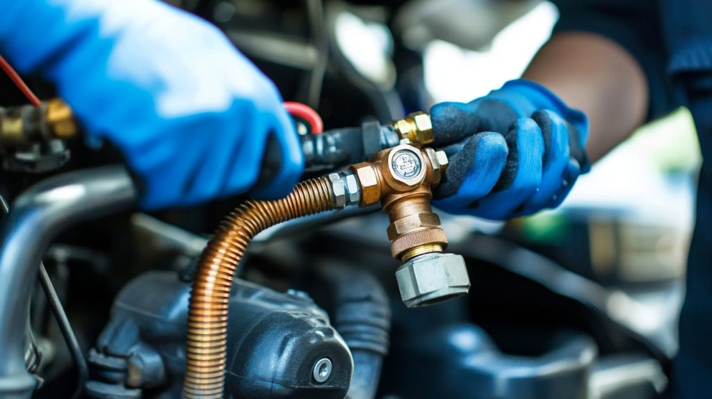
A properly installed air brake system is critical for the safety and efficiency of commercial trucks. Faulty air brake lines can lead to pressure leaks, delayed braking response, or catastrophic system failure. This guide provides a detailed, step-by-step walkthrough of air brake line installation, covering layout planning, sealing techniques, pressure testing, and essential safety protocols. Whether you’re a fleet technician or a DIY enthusiast, this guide ensures your truck’s air brake system operates reliably under heavy loads and harsh conditions.

Section 1: Tools and Materials Checklist
Before starting, gather these tools and components:
- Air brake tubing (nylon or DOT-approved steel, 1/4” to 1/2” diameter).
- Push-to-connect fittings or flared brass fittings (ensure compatibility with tubing material).
- Tube cutter and deburring tool (for clean, smooth cuts).
- Leak detection spray (soapy water or commercial aerosol).
- Pressure gauge and test pump (capable of 150 PSI).
- Cable ties and protective sleeves (abrasion-resistant).
- Torque wrench (for fitting tightening).
- Safety gloves and goggles (mandatory for high-pressure work).
Safety Note: Always depressurize the system before installation and wear PPE to avoid injury from sudden air releases.
Section 2: Planning the Air Line Layout
Step 1: Map the Air Flow Path
Start by identifying the air flow sequence:
- Air compressor → wet tank (moisture separator).
- Wet tank → primary/secondary dry tanks.
- Dry tanks → brake chambers (via relay valves).
Key Tip: Use color-coded tubing (e.g., blue for supply lines, red for emergency lines) to simplify troubleshooting.
Step 2: Avoid Common Routing Mistakes
- Prevent friction: Keep lines at least 1 inch away from moving parts (e.g., suspension components).
- Secure lines: Use nylon clamps every 12–18 inches to minimize vibration.
- Protect bends: Maintain a minimum bend radius of 5x the tube diameter to avoid kinking.
Section 3: Cutting and Preparing Tubing
Step 3: Measure and Cut with Precision
- Measure tubing lengths with a 10% margin for routing adjustments.
- Use a tube cutter (not a hacksaw) to ensure burr-free ends.
- Deburr the cut edges with a file or deburring tool.
Why It Matters: Rough edges can tear O-rings or create turbulence, leading to pressure drops.
Step 4: Install Protective Sleeves
Wrap tubing in abrasion-resistant sleeves where it passes through frame holes or near sharp edges.
Section 4: Sealing Connections
Step 5: Fitting Installation Techniques
- Push-to-connect fittings:
- Insert the tube until it bottoms out in the fitting.
- Pull back gently to lock the collet mechanism.
- Flared fittings:
- Slide the nut and ferrule onto the tube.
- Flare the tube end using a flaring tool.
- Tighten the nut to manufacturer specs (typically 15–20 ft-lbs).
Pro Tip: Apply a thin layer of PTFE-based lubricant to O-rings to ease assembly and prevent dry rot.
Step 6: Avoid Cross-Threading
Align fittings straight before tightening. If resistance is felt, unscrew and restart.
Section 5: Pressure Testing and Leak Detection
Step 7: Initial Pressure Test
- Close all drain valves and connect a test pump to the system.
- Gradually pressurize to 100 PSI and inspect for audible leaks.
Step 8: Soapy Water Test
Spray soapy water on every fitting and connection. Bubbles indicate leaks.
Critical Checkpoints:
- Gladhands (trailer connections).
- Brake chamber diaphragms.
- Valve stem seals.
Step 9: Full-System Test at 150 PSI
Raise pressure to 150 PSI (max operating pressure) and monitor for 10 minutes. A drop >5 PSI indicates unresolved leaks.
Section 6: Post-Installation Best Practices
Step 10: Label and Document
Label each line with heat-resistant tags (e.g., “Primary Supply,” “Emergency Line”). Update the truck’s maintenance log with installation dates and test results.
Step 11: Schedule Follow-Up Inspections
Recheck connections after 500 miles of operation, as vibration may loosen fittings.
Common Pitfalls and Fixes
- Leaking Push-to-Connect Fittings:
- Cause: Tube not fully inserted or debris in the collet.
- Fix: Disassemble, clean, and reinsert the tube.
- Kinked Tubing:
- Cause: Over-tightened clamps or sharp bends.
- Fix: Replace the damaged section and reroute with proper bend radius.
Conclusion
A meticulous air brake line installation ensures your truck’s braking system delivers consistent, reliable performance. By adhering to these steps—mapping the layout, sealing connections correctly, and rigorously testing for leaks—you’ll mitigate risks of brake failure and comply with DOT FMVSS 121 standards. Remember: Cutting corners during installation can lead to costly downtime or accidents. When in doubt, consult an ACME-certified technician or refer to OEM guidelines.
Need Professional-Grade Parts? Explore ACME’s DOT-certified air brake lines and fittings here, engineered for extreme durability and leak-free operation.

Introduction
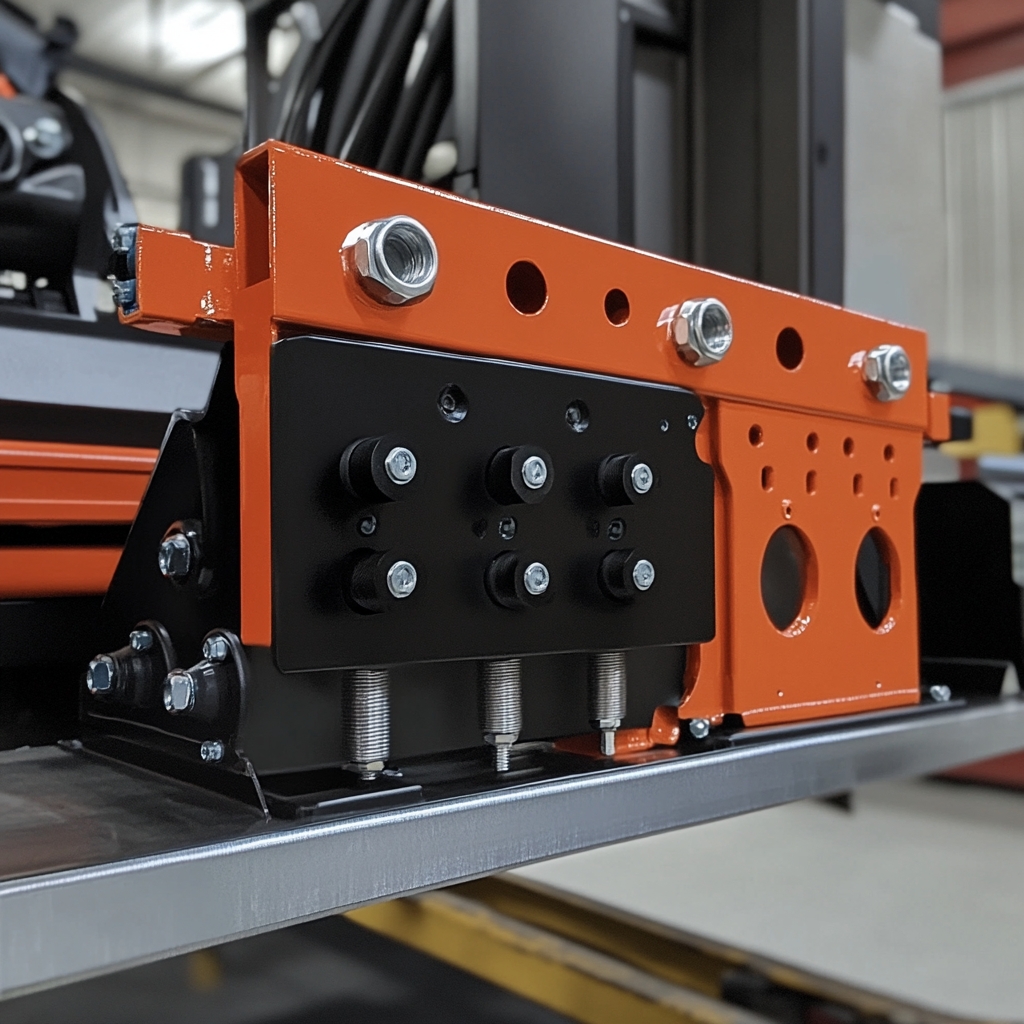
A poorly mounted air compressor can turn into a nightmare of rattling noises, premature belt wear, and even engine damage. Whether you’re retrofitting a new compressor or upgrading an existing setup, the bracket’s design, vibration isolation, and belt tension are critical to reliability. This guide dives into professional techniques for mounting air compressor brackets across diesel and gasoline engines, ensuring smooth operation and extended component life.
Section 1: Tools and Materials Checklist
Essential Tools:
- Torque wrench (20–50 ft-lb range).
- Dial caliper or shims (for gap measurement).
- Belt tension gauge or frequency analyzer.
- Anti-seize compound and threadlocker.
- Vibration-damping mounts (rubber, polyurethane, or hydraulic).
Bracket Materials:
- Cast steel: For heavy-duty diesel engines (e.g., Cummins ISX15).
- Aluminum alloy: Lightweight option for passenger vehicles.
- Adjustable brackets: Allow fine-tuning for aftermarket compressors.
Safety First:
- Disconnect the battery to avoid accidental engine starts.
- Use engine support bars when removing OEM brackets.
Section 2: Selecting the Right Bracket
Step 1: Match the Bracket to Engine Architecture
- Inline engines: Look for brackets with vertical mounting points (e.g., Detroit DD13).
- V-type engines: Opt for angled brackets that clear intake manifolds (e.g., Ford Power Stroke).
Key Tip: Cross-reference compressor and engine bolt patterns using OEM diagrams or ACME’s compatibility database [link].
Step 2: Verify Clearance and Load Capacity
- Measure clearance between the compressor pulley and fan/radiator (minimum 1 inch).
- Ensure the bracket’s load rating exceeds the compressor’s weight + belt tension forces.
Red Flag: Bending or flexing under load? Upgrade to a reinforced bracket.
Section 3: Installing Vibration-Damping Mounts
Step 3: Choose the Right Damping Material
- Rubber mounts: Budget-friendly for low-vibration gasoline engines.
- Polyurethane mounts: Higher durability for diesel applications.
- Hydraulic mounts: Ideal for high-RPM or turbocharged engines.
Pro Tip: Stiffness (measured in Shore hardness) should match engine vibration frequency.
Step 4: Mounting Process
- Isolate the Bracket: Place damping mounts between the bracket and engine block.
- Torque Gradually: Tighten bolts in a star pattern to 80% of final torque (e.g., 25 ft-lb), then recheck alignment.
- Final Torque: Apply OEM-spec torque (e.g., 35 ft-lb for Duramax LB7) with threadlocker.
Pitfall Alert: Over-compressed mounts lose damping efficiency. Use shims to maintain 10–15% compression.
Section 4: Calculating and Setting Belt Tension
Step 5: Measure Baseline Tension
- Use a Krikit II tension gauge:
- Place the gauge midway between pulleys.
- Press until the arrow aligns with the belt’s recommended deflection (e.g., 0.5” per 12” span).
- Frequency Method (for serpentine belts):
- Pluck the belt like a guitar string.
- Use a frequency app (e.g., Gates Sonic Tension) to match Hz to the target tension.
Step 6: Adjust for Operating Conditions
- Cold climates: Increase tension by 10% to offset belt contraction.
- High-load applications: Add 15% tension for heavy-duty compressors (e.g., train HVAC systems).
Formula:
T=g4×L×f2×W
Where T = tension (N), L = span length (m), f = frequency (Hz), W = belt mass (kg/m), g = gravity (9.81 m/s²).
Section 5: Post-Installation Validation
Step 7: Run Vibration Tests
- Start the engine and rev to 2,000 RPM.
- Use a vibration analyzer to measure bracket acceleration (aim for < 5 m/s²).
Problem Signs:
- Peaks at 50–100 Hz: Loose bracket bolts.
- Peaks > 200 Hz: Belt misalignment.
Step 8: Inspect Belt Wear Patterns
- Glazing: Over-tensioned belt (reduce tension by 10–15%).
- Cracking: Under-tensioned or aged belt (replace immediately).
Section 6: Troubleshooting Common Issues
Problem 1: Persistent Vibration Noise
- Causes:
- Incorrect mount stiffness (e.g., rubber mounts on a diesel).
- Resonance between engine and bracket.
- Fix: Swap to hydraulic mounts or add a tuned mass damper.
Problem 2: Rapid Belt Wear
- Causes:
- Pulley misalignment (use a laser alignment tool).
- Contaminated belt (oil/grease exposure).
- Fix: Clean pulleys with brake cleaner and realign.
Conclusion
Mounting an air compressor bracket isn’t a “bolt-on and forget” job—it’s a precision balancing act between mechanical stability and vibration control. By selecting the right bracket, isolating vibrations, and setting belt tension scientifically, you’ll eliminate noise complaints and slash maintenance costs. For fleet managers and rebuilders, investing 30 extra minutes in this process can add years to your compressor’s lifespan.
Upgrade Your Setup: Explore ACME’s vibration-optimized compressor brackets here, featuring laser-aligned mounting points and OEM-grade damping.

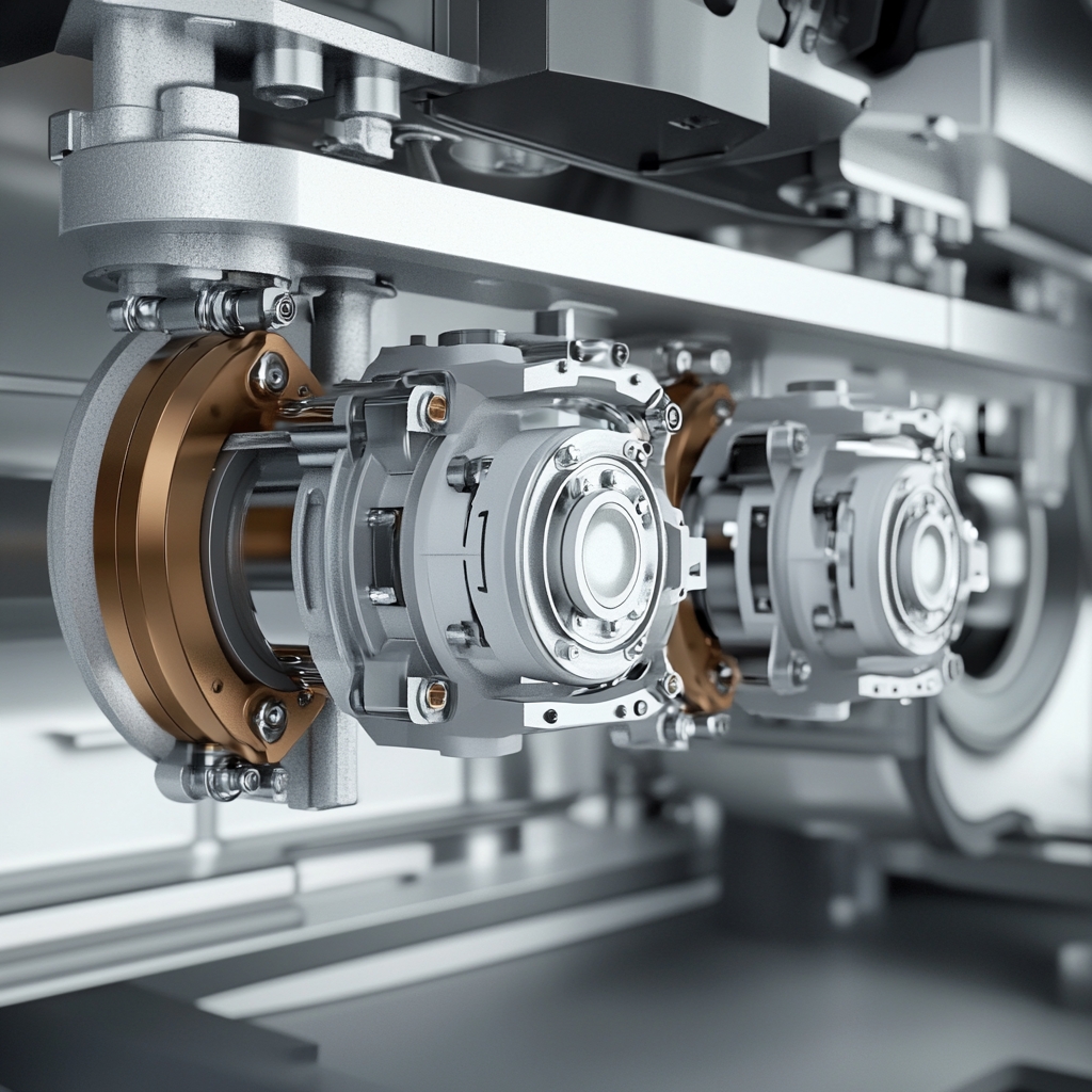
Introduction
Electronic Braking Systems (EBS) revolutionize commercial vehicle safety by blending pneumatic control with digital precision. Yet, improper valve installation can lead to erratic braking, fault codes, or even system lockouts. This guide breaks down EBS valve mounting, pneumatic/electrical integration, and ECU programming into 10 foolproof steps, ensuring your installation meets ISO 7638 and OEM standards. Perfect for fleet technicians and aftermarket retrofitters.

Section 1: Tools and Safety Precautions
Tools & Materials:
- EBS valve assembly (match ABS/EBS generation, e.g., WABCO EBS3 or Knorr-Bremse EBS 5).
- Torque wrench (5–25 Nm range).
- Pneumatic line crimper and DOT-approved tubing.
- 12V/24V compatible wiring harness (shielded, SAE J1128 rated).
- Diagnostic tool (e.g., ACME ProScan or Jaltest).
- Threadlocker (medium strength) and silicone grease.
Safety First:
- Depressurize air tanks and disconnect batteries.
- Wear safety glasses when handling high-pressure lines.
Section 2: 10-Step Installation Process
Step 1: Valve Positioning & Mounting
- Locate Mounting Points:
- Install near the brake chambers, avoiding heat sources (e.g., exhaust) and ensuring service access.
- Use OEM brackets or ACME universal brackets (adjustable for frame rails).
- Secure the Valve:
- Hand-tighten bolts, then torque to 15 Nm (e.g., Meritor EBS valves). Apply threadlocker.
Pro Tip: Leave 2+ inches between valves for heat dissipation and hose routing.
Step 2: Pneumatic Line Connections
- Primary/Secondary Circuits:
- Connect red lines (primary) and blue lines (secondary) to corresponding tank ports.
- Use ¼” tubing for control lines, ½” for supply lines.
- Crimp Fittings:
- Double-crimp all fittings and tug-test for security.
Critical Check: Verify O-rings are lubricated with silicone grease to prevent air leaks.
Step 3: Electrical Harness Wiring
- Pinout Verification:
- Match harness pins to valve connectors (e.g., CAN High/Low, 12V+, ground).
- Reference wiring diagrams (e.g., WABCO #12345678).
- Shielding & Grounding:
- Wrap harness in braided shielding, grounded to chassis (resistance <0.5 Ω).
Red Flag: Never route EBS wires parallel to alternator cables—cross at 90° angles.
Step 4: CAN Bus Integration
- Tap into Vehicle CAN:
- Locate the CAN bus connector (J1939 or J1708).
- Splice EBS valve CAN wires using solder-seal connectors.
- Termination Resistors:
- Confirm 120 Ω resistance across CAN lines (add resistors if missing).
Step 5: ECU Power-Up & Initialization
- Reconnect Batteries:
- Power on the ECU and wait 30 seconds for self-diagnosis.
- Clear Legacy Codes:
- Use the diagnostic tool to wipe previous fault codes.
Step 6: Upload Valve Configuration
- Load Valve Profile:
- Select the EBS valve’s firmware file (e.g., .VBF for WABCO).
- Flash Parameters:
- Set valve type (e.g., proportional/modulating), pressure limits, and response curves.
Pro Tip: For retrofits, use “Generic Truck” mode if OEM profiles are unavailable.
Step 7: Pneumatic Pressure Calibration
- Charge the System:
- Build air pressure to 120 PSI.
- Calibrate via Diagnostics:
- Follow tool prompts to set cut-in/cut-out pressures and balance primary/secondary circuits.
Step 8: Signal Validation
- Static Test:
- Command 50% brake application via the tool. Verify valve actuation (audible click).
- Dynamic Test:
- Drive at 20 mph and trigger emergency braking. Confirm ABS/EBS intervention.
Step 9: Leak-Down Test
- Parking Brake Test:
- Apply parking brake, then monitor pressure drop (<2 PSI per minute).
- Service Brake Test:
- Hold pedal for 2 minutes. Pressure drop >5 PSI indicates leaks.
Step 10: Final Documentation
- Print Calibration Report:
- Attach to the vehicle’s service history.
- Label Valves:
- Use heat-resistant tags (e.g., “EBS Primary – SN:12345”).
Section 3: Troubleshooting Common Issues
Problem 1: ECU Communication Failure
- Causes:
- CAN wiring incorrect or unshielded.
- Missing termination resistor.
- Fix: Recheck CAN resistance (60 Ω at each end) and shield grounding.
Problem 2: Delayed Brake Response
- Causes:
- Undersized pneumatic lines.
- Incorrect valve response curve.
- Fix: Upgrade to ½” lines and recalibrate valve ramp-up time.
Conclusion
Installing EBS valves demands precision in mechanical, electrical, and software domains—but the payoff is braking systems that blend safety with adaptability. By methodically following these 10 steps, you’ll dodge common pitfalls like signal noise or pressure leaks, ensuring compliance and driver confidence.
Upgrade Your Toolkit: Explore ACME’s EBS retrofit kits here, featuring pre-terminated harnesses and plug-and-play valve profiles.

Introduction:
In sub-zero temperatures, air brake systems face a deadly threat: ice. Condensation in air lines can freeze, blocking pressure flow and crippling braking performance. For truckers and fleet managers operating in Arctic climates, a single frozen line can mean stranded cargo, costly downtime, or even accidents. This guide delivers battle-tested strategies to winterize air brake systems, combining heated air dryers, insulated lines, and freeze-resistant valves to ensure reliability at -40°F/C.

Section 1: Tools and Materials Checklist
Winterization Essentials:
- Heated air dryer (e.g., ACME FrostGuard Pro with 12V/24V compatibility).
- Self-sealing foam insulation (1/2” wall thickness, rated for -50°F).
- Electric heated drain valves (auto-cycling or manual override).
- Silicone spray (for rubber component protection).
- Pressure tester (0–200 PSI range).
- Heat gun (for insulation adhesion in cold environments).
Safety Gear:
- Insulated gloves (to handle metal components at extreme temps).
- Circuit tester (to prevent electrical shorts during dryer install).
Section 2: Installing a Heated Air Dryer
Step 1: Choose the Right Dryer
- Compressor Compatibility: Match dryer CFM rating to the compressor’s output (e.g., 18 CFM dryer for a 15 CFM compressor).
- Power Source: Opt for 24V systems in heavy-duty trucks to handle higher amperage.
Step 2: Mounting the Dryer
- Location: Install downstream of the compressor but before the wet tank. Avoid engine hotspots (>200°F).
- Secure the Bracket: Use vibration-damping mounts to prevent fatigue cracks.
- Wiring: Connect to a fused ignition-switched circuit. Use 10-gauge wire for runs >3 feet.
Pro Tip: Add a manual bypass valve for emergency operation if the dryer fails.
Section 3: Insulating Air Lines
Step 3: Select Insulation Materials
- Closed-cell foam: Prevents moisture absorption (critical for aluminum lines).
- Fiberglass sleeves: For high-heat zones near the exhaust.
- Adhesive-backed insulation: Simplifies application on curved surfaces.
Step 4: Insulation Installation
- Clean Lines: Wipe lines with isopropyl alcohol to remove grease.
- Wrap Tightly: Spiral-cut insulation for bends and secure with UV-resistant zip ties.
- Seal Joints: Apply silicone tape at fittings to block cold air ingress.
Critical Areas:
- Gladhands: Double-layer insulation with removable covers for coupling.
- Brake Chambers: Use pre-molded neoprene covers with adhesive flaps.
Section 4: Upgrading Drain Valves
Step 5: Install Heated Drain Valves
- Electric Heating Elements: Ideal for automatic moisture expulsion (e.g., ACME AutoDrain 24V).
- Pneumatic Valves: Use compressed air to cycle drains (no electrical dependency).
Installation Steps:
- Replace OEM drain valves on wet tanks and reservoirs.
- For electric valves: Wire to a timer circuit (e.g., cycle every 30 minutes).
- For pneumatic valves: Connect to the parking brake circuit for post-trip draining.
Winter Mode: Adjust valve cycle frequency based on humidity (daily in coastal climates).
Section 5: Anti-Freeze Additives and Lubrication
Step 6: Apply Silicone Spray
- Spray on rubber hoses, O-rings, and diaphragm seals to prevent brittleness.
Step 7: Use Alcohol-Based Air Line Antifreeze
- Methanol Injection: Add 1–2 oz. per 100 gallons of air tank capacity.
- Caution: Avoid isopropyl alcohol—it can degrade polyurethane components.
Section 6: Post-Installation Testing
Step 8: Pressure Drop Test
- Charge the system to 120 PSI.
- Let sit overnight in freezing temps.
- Acceptable drop: <5 PSI over 8 hours.
Step 9: Ice Simulation Test
- Spray water on gladhands and valves, then freeze to -20°F. Verify no blockages during brake application.
Section 7: Troubleshooting Frozen Brake Systems
Problem 1: Frozen Gladhands
- Quick Fix: Use a portable heat blanket or engine coolant-fed thawing kit.
Problem 2: Ice in Air Dryer
- Cause: Overloaded dryer or saturated desiccant.
- Fix: Replace desiccant and install a pre-cooler coil upstream.
Conclusion
Winterizing air brake systems isn’t optional in extreme climates—it’s a lifeline. By integrating heated dryers, armored insulation, and smart drain valves, fleets can conquer ice-bound routes with confidence. Remember: Proactive winter prep costs far less than a single freeze-related breakdown.
Need Arctic-Grade Parts? Explore ACME’s winterization kits here, featuring plug-and-play heated dryers and NSF-certified insulation.

Introduction:
A secure connection between a tractor and trailer’s air brake systems is non-negotiable for safe heavy-duty operations. Faulty gladhands—the pneumatic couplers linking tractor and trailer—can lead to brake lag, pressure loss, or catastrophic detachment. Governed by ISO 7638, these connectors demand strict adherence to color coding, dimensional specs, and seal integrity. This guide dives into gladhands installation, compatibility testing, and synchronization under ISO 7638, empowering fleets to avoid DOT violations and keep highways safe.
Section 1: ISO 7638 Gladhands Overview
Key Requirements:
- Color Coding:
- Red: Emergency/Parking Brake Line (ISO 7638-1).
- Blue: Service Brake Line (ISO 7638-2).
- Yellow: Auxiliary Functions (e.g., trailer ABS).
- Dimensional Specs:
- ½” NPT threads for North America.
- M22x1.5 threads for European trailers.
- Seal Design: Double-lip rubber seals to withstand 150 PSI and -40°F to 200°F temperatures.
Safety First:
- Always depressurize air systems before disconnecting gladhands.
- Wear gloves to avoid pinch injuries during coupling.
Section 2: Tools and Materials
Installation Kit:
- ISO 7638-compliant gladhands (e.g., Haldex 247065 for red, 247066 for blue).
- Torque wrench (15–25 ft-lb range).
- Teflon tape or thread sealant (SAE J524-approved).
- Leak detection spray (soapy water or commercial aerosol).
- Pressure gauges (0–200 PSI) for synchronization testing.
Section 3: Step-by-Step Gladhands Installation
Step 1: Verify Compatibility
- Match Colors: Ensure tractor and trailer gladhands follow ISO 7638 color codes.
- Check Threads: Confirm NPT vs. M22 compatibility—mismatched threads cause cross-threading.
Pro Tip: Use adapters (e.g., Dixon ½” NPT to M22) for cross-regional trailers.
Step 2: Prepare Threads
- Clean male/female threads with a wire brush.
- Apply Teflon tape clockwise (2–3 wraps) or thread sealant.
Step 3: Torque Connections
- Hand-tighten gladhands, then torque to 20 ft-lb.
- Avoid over-tightening—it deforms seals and causes leaks.
Section 4: Seal Integrity Testing
Step 4: Pressure Test
- Charge the tractor’s air system to 120 PSI.
- Connect gladhands and trailer lines.
- Monitor pressure for 5 minutes—drop >2 PSI indicates leaks.
Step 5: Soapy Water Test
- Spray soap solution on connected gladhands.
- Bubbles reveal leaks at threads or seals.
Fix Leaks:
- Replace cracked seals (e.g., Timken 569947).
- Reapply thread sealant and retorque.
Section 5: Brake Synchronization Testing
Step 6: Primary/Secondary Circuit Sync
- Primary Circuit (Blue):
- Apply 60 PSI via brake pedal. Trailer service brakes should engage within 0.3 seconds.
- Emergency Circuit (Red):
- Activate parking brake. Trailer brakes must lock within 1 second.
Step 7: Auxiliary Line Validation (Yellow)
- Test trailer ABS signal continuity with a multimeter (expected: 12V with ignition on).
- Use a diagnostic scanner to confirm ABS module communication.
Section 6: Common Failures and Fixes
Problem 1: Cross-Threaded Gladhands
- Symptoms: Difficulty hand-tightening, air leaks.
- Fix: Replace damaged gladhands and threads.
Problem 2: Seal Degradation
- Causes: UV exposure, chemical corrosion.
- Fix: Install UV-resistant seals (e.g., Parker Hannifin 2-226).
Problem 3: Pressure Lag
- Causes: Undersized air lines or kinked hoses.
- Fix: Upgrade to ½” DOT-approved hoses and reroute lines.
Section 7: Compliance and Documentation
- DOT Inspection Prep: Keep records of gladhands part numbers, torque values, and test results.
- Labeling: Tag gladhands with installation dates and technician initials.
Conclusion
ISO 7638 isn’t just a regulatory hoop—it’s a blueprint for fail-safe tractor-trailer braking. By rigorously testing gladhands compatibility, seal integrity, and synchronization, fleets can prevent roadside inspections from turning into costly shutdowns. Remember: A 10-minute pressure test today could avert a jackknife tomorrow.
Upgrade Your Fleet: Explore ACME’s ISO 7638-certified gladhands kits here, featuring pre-lubricated seals and corrosion-resistant alloys.

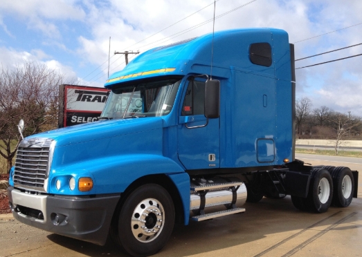
List of American Truck Brands & Best-Selling Models (2000)
| Brand | Top-Selling Model | Key Features |
|---|---|---|
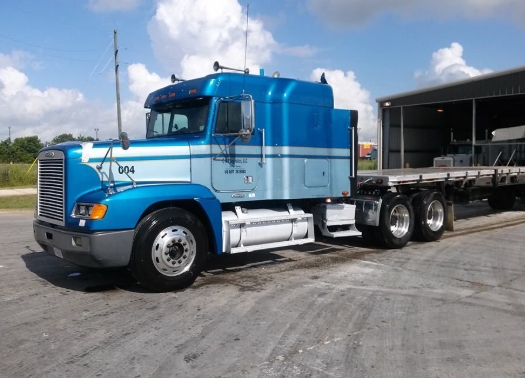
| 1. Freightliner | Century Class S/T | Detroit Diesel Series 60 engine (12.7L), integrated sleeper cab, fuel-efficient design. |
| 2. International | 9400 Eagle | Navistar DT466 engine (7.6L), iconic long-nose design, favored for long-haul routes. |
| 3. Peterbilt | 379 | Caterpillar C15 engine (15L), classic aerodynamic hood, owner-operator favorite. |
| 4. Kenworth | W900 | Cummins N14 engine (14L), customizable configurations, rugged durability. |
| 5. Ford | CL9000 | Ford Power Stroke V8 (7.3L), versatile medium-duty workhorse for regional hauling. |
| 6. Western Star | 4900 | Detroit Diesel Series 60 (12.7L), heavy-duty chassis for vocational/off-road use. |
| 7. GMC | C-Series | GM 6.5L Turbo Diesel, lightweight design for urban delivery and utility fleets. |
Market Highlights (2000)
- Market Leaders: Freightliner dominated North America with ~30% market share, driven by fuel-efficient designs.
- Engine Wars: Detroit Diesel vs. Caterpillar rivalry shaped performance preferences.
- Owner-Operator Culture: Peterbilt 379 and Kenworth W900 became symbols of American trucking pride.
- Declining Models: GMC C-Series faced phase-out as medium-duty demand shifted to Ford and International.


