
Introduction Modern Anti-Lock Braking Systems (ABS) are critical for maintaining control and stability in heavy-duty trucks, especially under adverse road conditions. However, the reliability of ABS hinges on two often-overlooked factors: sensor-module compatibility and electromagnetic signal integrity. This blog dives deep into the technical challenges of ABS components, strategies for preventing signal interference, and best practices...


The fuel injection pump is the heart of a diesel engine’s fuel system, responsible for delivering precise amounts of pressurized fuel to the injectors at the correct timing. For engines like the Dongfeng Cummins 3960418 (part of the BYC CPES6AD95D320/3RS2110 series), ensuring the injection pump’s integrity is critical for performance, efficiency, and longevity. In this guide, we’ll break down everything you need to know about the Fuel Injection Pump 10 402 446 019 (10402446019), including installation, maintenance, troubleshooting, and its role in the engine ecosystem.
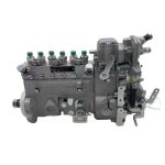
Understanding the Fuel Injection Pump 10 402 446 019
Key Specifications
- Part Number: 10 402 446 019 / 10402446019
- Compatibility: Designed for Dongfeng Cummins 3960418 engines, commonly used in heavy-duty trucks, construction machinery, and industrial applications.
- Type: Rotary or inline pump (varies by application).
- Pressure Rating: Typically operates at 1,800–2,200 psi (125–150 bar).
- OEM Equivalents: Cross-references to Cummins OEM part numbers and aftermarket alternatives (e.g., Bosch, Delphi).
Role in the Engine
- Fuel Delivery: Pressurizes diesel and distributes it to injectors.
- Timing Control: Synchronizes fuel injection with engine timing (crankshaft/camshaft position).
- Emission Compliance: Ensures precise fuel metering to meet emissions standards (e.g., Euro III/IV).
Compatibility & Applications
Dongfeng Cummins 3960418 Engine
- Engine Series: BYC CPES6AD95D320/3RS2110.
- Displacement: 6.7L or similar, depending on configuration.
- Common Vehicles/Equipment:
- Dongfeng Tianjin/Kingrun trucks.
- Construction machinery (excavators, loaders).
- Power generators.
Cross-Referencing the Pump
Verify compatibility using:
- Cummins QuickServe Online: Input the engine serial number for OEM confirmation.
- Aftermarket Databases: Cross-check with Bosch 0445010032 or Delphi HPI-476.
Installation Guide for Fuel Injection Pump 10 402 446 019
Tools Required
- Torque wrench (20–100 Nm range).
- Timing lock kit (for engine-specific timing marks).
- Fuel pressure gauge (0–3,000 psi).
- Seal puller and OEM gasket/seal kit.
Step-by-Step Installation
- Pre-Installation Checks:
- Drain fuel system to prevent contamination.
- Inspect the new pump for damage or missing components.
- Timing Alignment:
- Rotate the engine to Top Dead Center (TDC) on cylinder 1.
- Align the pump’s timing mark with the engine’s gear mark (refer to OE manuals).
- Pump Installation:
- Mount the pump and torque bolts to 25–30 Nm (Cummins spec).
- Connect fuel lines and priming pump.
- Priming & Bleeding:
- Use a hand primer to purge air from the system.
- Start the engine and check for leaks or irregular idle.
Common Issues & Troubleshooting
Symptoms of a Failing Injection Pump
- Hard Starting: Air ingress or low pressure due to worn seals.
- Power Loss: Sticking plungers or incorrect timing.
- Excessive Smoke: Over-fueling (black smoke) or timing misalignment (white smoke).
- Fuel Leaks: Damaged O-rings or housing cracks.
Diagnostic Steps
- Fuel Pressure Test: Use a gauge to verify pump output (target: 1,800+ psi).
- Leak-Off Test: Check injector return flow rates (abnormal flow = pump/injector issues).
- Scan Tool Analysis: Read fault codes for timing deviations (e.g., P0251 for pump circuit malfunctions).
Maintenance Tips for Longevity
Preventative Measures
- Fuel Quality: Use ultra-low-sulfur diesel (ULSD) to prevent pump wear.
- Regular Filter Changes: Replace fuel filters every 15,000 km to avoid clogging.
- Seal Inspections: Check O-rings and gaskets during routine servicing.
Carbon Deposit Management
Carbon buildup in the fuel system can disrupt pump performance. Mitigate this with:
- Fuel Additives: Use diesel injector cleaners (e.g., Liqui Moly Diesel Purge).
- Ultrasonic Cleaning: For severe deposits, disassemble and clean pump components.
Synergy with Timing Systems & Injectors
Timing Coordination
The injection pump relies on precise engine timing to function correctly. A misaligned timing belt/chain can cause:
- Retarded Injection: Reduced power and increased emissions.
- Advanced Injection: Engine knocking or piston damage.
Pro Tip: After replacing the timing belt/chain, always recheck injection pump timing.
DPI/CRDi Injector Testing
Modern Cummins engines often use Common Rail Direct Injection (CRDi) or Direct Pneumatic Injection (DPI) systems. Pair pump maintenance with:
- Injector Flow Testing: Ensure injectors deliver fuel evenly.
- Nozzle Cleaning: Remove carbon deposits via walnut blasting or chemical solvents.
Case Study: Pump Failure in a Dongfeng Truck
A 2018 Dongfeng Kingrun truck (3960418 engine) exhibited rough idling and power loss. Diagnostics revealed:
- Root Cause: Worn plungers in the 10402446019 pump due to contaminated fuel.
- Repair: Replaced pump, installed new filters, and flushed the fuel system.
- Result: Restored 15% horsepower and eliminated smoke emissions.
Where to Source Reliable Replacement Pumps
- OEM Suppliers: Cummins-authorized dealers for genuine parts.
- Aftermarket Brands: Bosch, Delphi, or Denso for cost-effective alternatives.
- Avoid Counterfeits: Verify part numbers and holograms on packaging.
Conclusion
The Fuel Injection Pump 10 402 446 019 is a critical component for the Dongfeng Cummins 3960418 engine. Proper installation, timing alignment, and preventative maintenance can prevent costly breakdowns and ensure optimal performance. By integrating pump care with timing system checks and injector servicing, you’ll maximize the engine’s lifespan and efficiency.
Need Assistance? Consult Cummins service manuals or a certified diesel technician for complex repairs.
Hashtags:
#CumminsEngine #FuelInjectionPump #DieselMaintenance #HeavyDutyTrucks #EngineRepair
This guide equips mechanics and fleet managers with actionable insights to master fuel system maintenance—keeping engines running smoothly, mile after mile. 🚚💨
Internal combustion engines (ICEs) stand as remarkable feats of engineering, transforming fuel into mechanical energy with precision and power. At the heart of every engine lies a complex assembly of core components, each playing a critical role in the combustion process and power generation. This comprehensive technical analysis delves into the essential engine parts, their functions, advanced materials, and the ongoing innovations that are shaping the future of powertrain technology.


1. The Fundamental Role of Engine Components
Engine components work in perfect synchronization to convert chemical energy from fuel into mechanical power. These parts can be categorized into several functional groups:
- Power generation components (pistons, crankshaft, connecting rods)
- Air/fuel delivery systems (intake valves, fuel injectors, throttle body)
- Exhaust and emission control (exhaust valves, catalytic converters, EGR systems)
- Lubrication and cooling (oil pump, water pump, radiator)
- Timing and control systems (camshafts, timing belts/chains, sensors)
Technical significance: Modern engines achieve thermal efficiencies of 25-40%, with advanced designs pushing toward 50% efficiency through innovative component designs.
2. Core Engine Components and Their Functions
2.1 Pistons and Piston Rings
Piston Design and Materials:
- Aluminum alloys: Lightweight (2.5-3.0 kg per piston) with high thermal conductivity
- Forged vs. cast construction: Forged pistons offer superior strength for high-performance applications
- Coatings: Thermal barrier coatings (ceramic) and oil-shedding polymers
Piston Ring Functions:
- Compression rings: Seal combustion chamber (typically 2-3 rings per piston)
- Oil control rings: Regulate oil film thickness on cylinder walls
- Materials: High-carbon steel with molybdenum or chrome plating
Performance metrics:
- Piston speed: Up to 25 m/s in high-revving engines
- Temperature resistance: Up to 350°C surface temperature
2.2 Crankshaft and Connecting Rods
Crankshaft Construction:
- Forged steel: High-strength alloy steels (e.g., SAE 4340)
- Counterweights: Precision-balanced to reduce vibrations
- Main bearings: Journal diameters typically 50-100 mm
Connecting Rod Features:
- I-beam cross-section: Optimized strength-to-weight ratio
- Powder metallurgy: Used for high-performance small-end bearings
- Material: Forged steel or aluminum alloys for lightweight applications
Load specifications:
- Maximum combustion pressure: 15-20 MPa in turbocharged engines
- Bending stress: Up to 1,000 MPa during peak operation
2.3 Cylinder Block and Head
Block Materials and Design:
- Cast iron: Traditional material with excellent wear resistance
- Aluminum alloys: Lightweight (30-40% weight reduction vs. iron)
- Closed-deck design: Enhanced cylinder rigidity for high boost applications
Cylinder Head Features:
- Multi-valve configurations: 4-5 valves per cylinder for improved breathing
- Variable valve timing (VVT): Camshaft phasing mechanisms
- Material: Aluminum alloys with sodium-filled exhaust valves
Thermal management:
- Cooling jacket design: Optimized flow paths for coolant circulation
- Thermal barrier coatings: Reduce cylinder head surface temperatures by 50-100°C
3. Air/Fuel Delivery and Combustion Systems
3.1 Intake and Exhaust Valves
Valve Materials and Coatings:
- Intake valves: Silchrome-plated steel for corrosion resistance
- Exhaust valves: Inconel alloys or Stellite-facing for high-temperature endurance
- Sodium-filled exhaust valves: Improved heat dissipation
Valve Train Components:
- Rocker arms: Roller-tip designs reduce friction
- Valve springs: Dual-spring configurations prevent surge at high RPM
- Variable valve lift (VVL): Cam profile switching mechanisms
Performance specifications:
- Valve lift: 8-12 mm in modern engines
- Operating temperature: Up to 800°C for exhaust valves
3.2 Fuel Injection Systems
Injection Technologies:
- Direct injection (DI): 2,000-3,000 bar fuel pressure
- Port fuel injection (PFI): Lower pressure (3-5 bar)
- Gasoline direct injection (GDI): Piezo-electric injectors with 5-7 hole nozzles
Fuel Pump Systems:
- High-pressure pumps: Plunger-type with camshaft drive
- Common rail systems: Accumulator design for precise pressure control
- Electric fuel pumps: 2-5 bar for PFI systems
Emission control integration:
- Lean-burn combustion: Requires precise air/fuel ratio control
- Exhaust gas recirculation (EGR): Cooled EGR systems for NOx reduction
3.3 Turbocharging and Supercharging
Turbocharger Components:
- Turbine wheel: Inconel alloys for high-temperature operation
- Compressor wheel: Aluminum alloys with optimized blade geometry
- Bearing systems: Floating journal bearings or ball bearings
Supercharger Types:
- Roots type: Positive displacement, high boost at low RPM
- Twin-screw: Continuous compression with higher efficiency
- Centrifugal: Similar to turbochargers but belt-driven
Performance metrics:
- Boost pressure: Up to 3.5 bar in performance applications
- Efficiency gains: 20-30% power increase with forced induction
4. Lubrication and Cooling Systems
4.1 Lubrication System Components
Oil Pump Designs:
- Gear pumps: Simple, reliable design for most applications
- Variable displacement pumps: Adjust flow based on engine load
- Electric oil pumps: For start-stop systems and hybrid applications
Oil Filter Technologies:
- Full-flow filters: Remove 98% of contaminants >25μm
- Bypass filters: Capture particles down to 1-2μm
- Magnetic filters: Capture ferrous particles
Lubricant specifications:
- Viscosity grades: 0W-20 to 10W-60 depending on climate and load
- Additives: Detergents, anti-wear agents, viscosity modifiers
4.2 Cooling System Components
Water Pump Designs:
- Mechanical pumps: Belt-driven with impeller designs
- Electric pumps: Precise flow control for start-stop systems
- Variable speed pumps: Adjust flow based on coolant temperature
Radiator and Heat Exchangers:
- Aluminum radiators: Lightweight with high heat dissipation
- Oil coolers: Integrated or standalone designs
- Intercoolers: Air-to-air or air-to-water for charge air cooling
Coolant specifications:
- Ethylene glycol-based: Typical 50/50 mix with water
- Organic acid technology (OAT): Extended-life coolants
- Nanofluids: Advanced coolants with enhanced thermal properties
5. Timing and Valve Control Systems
5.1 Camshaft and Timing Components
Camshaft Materials and Design:
- Forged steel: High-strength for performance applications
- Cast iron: Cost-effective for standard engines
- Variable valve timing (VVT): Phasing mechanisms with hydraulic or electric actuators
Timing Belt/Chain Systems:
- Timing belts: Fiber-reinforced rubber with tensioner systems
- Timing chains: Roller chains with hydraulic tensioners
- Chain guides: Polymer or metal designs to reduce noise
Performance specifications:
- Cam lift: 8-15 mm depending on engine design
- Valve timing variation: ±1° crank angle precision
5.2 Variable Valve Timing and Lift Systems
VVT Technologies:
- Hydraulic VVT: Oil-pressure actuated phasers
- Electric VVT: Precise motor-driven control
- Camless systems: Fully electronic valve actuation
VVL (Variable Valve Lift) Systems:
- BMW Valvetronic: Continuously variable lift control
- Honda VTEC: Switching between high/low lift profiles
- Ferrari Variable Lift: Advanced electro-hydraulic systems
Benefits:
- Improved fuel efficiency (10-20% gains)
- Enhanced low-end torque and high-RPM power
- Reduced emissions through optimized combustion
6. Advanced Materials and Manufacturing Innovations
6.1 Lightweight Materials
Aluminum Alloys:
- 319 alloy: Common for engine blocks (good castability)
- 356 alloy: Improved mechanical properties
- A356-T6: Heat-treated for higher strength
Magnesium Alloys:
- AZ91D: Used for valve covers and other non-critical parts
- WE43: High-temperature magnesium alloys for exhaust components
Titanium Alloys:
- Ti-6Al-4V: Used in high-performance valves and connecting rods
- Beta-C: Advanced titanium alloys for extreme applications
6.2 Additive Manufacturing
3D-Printed Components:
- Complex manifold designs: Optimized flow paths
- Lightweight brackets: Topology-optimized structures
- Prototyping: Rapid development of new designs
Direct Metal Laser Sintering (DMLS):
- Stainless steel and Inconel parts: For high-temperature applications
- Titanium components: Reduced weight with maintained strength
6.3 Precision Manufacturing Techniques
CNC Machining:
- 5-axis machining: Complex part geometries
- High-speed machining: Improved surface finish
- Micro-machining: For small precision components
Casting Technologies:
- Die casting: High-volume production of aluminum parts
- Sand casting: For large, complex components
- Investment casting: Precision parts with excellent surface finish
7. Testing and Validation of Engine Components
7.1 Component-Level Testing
Piston and Ring Testing:
- Firing tests: Simulated combustion conditions
- Friction testing: Ring/bore interaction analysis
- Thermal cycling: Thermal shock resistance
Crankshaft Testing:
- Bending fatigue tests: 10^8 cycles minimum
- Surface durability tests: Scuffing resistance evaluation
- Balancing verification: ±1gmm imbalance tolerance
7.2 System-Level Validation
Engine Dynamometer Testing:
- Power and torque measurement: ±1% accuracy
- Emission testing: CO, HC, NOx, PM measurements
- Fuel consumption analysis: BSFC (Brake Specific Fuel Consumption)
Endurance Testing:
- 1,000-hour durability tests: Simulated real-world conditions
- Cold start testing: -30°C ambient conditions
- High-altitude testing: Up to 5,000m equivalent
7.3 Virtual Validation Methods
Finite Element Analysis (FEA):
- Stress analysis: Predict component failure points
- Thermal analysis: Heat dissipation modeling
- Vibration analysis: NVH (Noise, Vibration, Harshness) prediction
Computational Fluid Dynamics (CFD):
- Airflow optimization: Intake and exhaust port design
- Combustion simulation: Flame propagation modeling
- Cooling system analysis: Coolant flow distribution
8. Future Trends in Engine Component Development
8.1 Electrification and Hybridization
48V Mild Hybrid Systems:
- Belt-integrated starter generators (BISG)
- P0/P2 hybrid configurations
- Regenerative braking integration
High-Voltage Components:
- Electric water pumps: Reduced parasitic losses
- Electric oil pumps: Precise lubrication control
- Integrated starter generators (ISG)
8.2 Alternative Fuels and Combustion Concepts
Gasoline Compression Ignition (GCI):
- Lean-burn combustion: Improved efficiency
- Advanced injection timing: Controlled auto-ignition
- EGR optimization: Reduced NOx emissions
Hydrogen Internal Combustion Engines (H2-ICE):
- Modified fuel systems: High-pressure hydrogen delivery
- Combustion chamber redesign: Flame speed optimization
- Materials compatibility: Hydrogen embrittlement resistance
8.3 Advanced Manufacturing and Materials
Additive Manufacturing:
- Complex cooling channel designs
- Topology-optimized components
- Rapid prototyping of new designs
Nanomaterials and Coatings:
- Diamond-like carbon (DLC) coatings: Reduced friction
- Thermal barrier coatings: Improved heat management
- Self-healing materials: Crack repair capabilities
Conclusion: The Heart of Modern Transportation
Engine components represent the pinnacle of mechanical engineering, combining precision design, advanced materials, and innovative manufacturing to deliver reliable power generation. As the automotive industry evolves toward electrification and alternative fuels, these components continue to adapt, incorporating new technologies to meet ever-stricter efficiency and emission standards.
Key takeaways:
- Modern engines integrate dozens of precisely engineered components working in harmony
- Advanced materials and manufacturing are pushing performance boundaries
- Electrification is transforming traditional engine architectures
- Sustainability drives innovation in component design and materials
Final thought: While electric vehicles capture headlines, the internal combustion engine remains a remarkable engineering achievement. The ongoing evolution of engine components ensures this technology will continue playing a vital role in global transportation for decades to come, even as it evolves to meet new challenges and opportunities.
Call to Action
🔧 Interested in engine component technologies?
⚙️ Explore our advanced engineering solutions for next-generation powertrains
📊 Request detailed specifications on our latest high-performance components
#EngineTechnology #AutomotiveEngineering #PowertrainInnovation #InternalCombustion #AdvancedMaterials #ManufacturingExcellence #SustainableMobility #FutureOfTransportation
Quisque tempor urna sed metus lobortis, vitae posuere lacus varius. Curabitur justo velit, laoreet vel tristique quis, aliquam nec nisl. Vestibulum vel arcu nunc.
In modern vehicle engineering, engine mounts represent deceptively simple yet critically important components that bridge the powertrain and chassis while mitigating harmful vibrations. These engineered interfaces must simultaneously secure the engine with precise stiffness, dampen vibrational energy across a broad frequency spectrum, and accommodate dynamic movements during operation. This comprehensive technical analysis explores the multifaceted world of engine mounts, examining their functional principles, advanced material formulations, dynamic performance characteristics, and the ongoing innovations that are redefining powertrain mounting systems for next-generation vehicles.


1. Fundamental Role of Engine Mounts in Vehicle Dynamics
Engine mounts serve as the critical connection points between the engine/transmission assembly and the vehicle chassis, performing several essential functions:
- Vibration isolation: Attenuating engine-generated vibrations to prevent transmission to the passenger compartment
- Load securing: Withstanding static and dynamic forces while maintaining precise engine positioning
- Misalignment compensation: Accommodating thermal expansion and dynamic movements during operation
- Noise reduction: Preventing structure-borne noise propagation through the chassis
Technical significance: Modern engine mounts can reduce vibration transmission by up to 95% compared to rigid mounting systems, directly contributing to cabin comfort and component longevity.
2. Types of Engine Mounts and Their Functional Characteristics
Contemporary vehicles employ various mount configurations optimized for specific performance requirements:
2.1 Conventional Rubber Mounts
- Design: Solid rubber elements vulcanized between metal inserts
- Characteristics:
- Simple, cost-effective construction
- Frequency-dependent stiffness (higher stiffness at high frequencies)
- Limited damping capability
- Applications: Basic passenger vehicles, non-critical mounting locations
2.2 Hydraulic Mounts (Hydromounts)
- Design: Fluid-filled chambers with internal baffles or pistons
- Advanced features:
- Frequency-tunable damping characteristics
- Active damping in response to vibration amplitude
- Multi-stage stiffness transitions
- Performance metrics:
- Effective frequency range: 5-200 Hz
- Damping force: Up to 500 N at peak excitation
2.3 Active Vacuum Mounts
- Design: Vacuum-controlled internal chambers with diaphragm actuators
- Technical specifications:
- Response time: <50 ms for stiffness modulation
- Control range: 5-10x stiffness variation
- Power consumption: 10-20W continuous operation
- Advanced capabilities:
- Closed-loop control via CAN bus signals
- Adaptive damping based on driving conditions
- Integration with vehicle dynamics control systems
2.4 Electromagnetic Mounts
- Design: Ferrofluid-filled chambers with electromagnetic coils
- Innovative features:
- Real-time stiffness adjustment through magnetic field control
- Ultra-fast response times (<10 ms)
- Programmable damping profiles
- Performance advantages:
- 20-30% better vibration isolation than hydraulic mounts
- Potential for predictive control algorithms
3. Advanced Material Formulations and Engineering Innovations
3.1 Rubber Compound Developments
- High-damping elastomers: Specially formulated synthetic rubbers with tailored loss factors
- Nanocomposite materials: Graphene or carbon nanotube reinforcements for enhanced fatigue resistance
- Temperature-resistant formulations: Operating range extended to -50°C to +150°C
Material innovation: Some premium mounts now use shape-memory alloys that adapt their stiffness characteristics based on temperature and load conditions.
3.2 Fluid Dynamics in Hydraulic Mounts
- Baffle optimization: Computational fluid dynamics (CFD) modeling for optimal flow restriction
- Low-viscosity fluids: Synthetic oils with stable viscosity across temperature ranges
- Anti-aeration designs: Preventing foam formation during high-amplitude vibrations
Performance enhancement: Advanced hydromounts incorporate multiple fluid chambers with progressive damping characteristics for broadband vibration control.
3.3 Structural Interface Design
- Finite element analysis (FEA): Optimized mounting bracket geometries for stress distribution
- Surface treatments: Plasma coating for improved metal-rubber adhesion
- Composite materials: Carbon fiber-reinforced plastic (CFRP) brackets for weight reduction
Design consideration: Modern mounts incorporate preloaded rubber elements to minimize initial deflection and maintain precise engine positioning.
4. Dynamic Performance Characteristics and Testing
4.1 Vibration Isolation Mechanisms
- Mass-spring-damper model: Mathematical representation of mount behavior
- Frequency-dependent stiffness: Non-linear stiffness curves for broadband isolation
- Transient response characteristics: Damping of impulse vibrations from engine start/stop
Performance metrics:
- Transmissibility ratio <0.2 at target frequencies (typically 8-25 Hz)
- Dynamic stiffness variation <15% over operating temperature range
- Fatigue life >10 million cycles
4.2 Testing and Validation Protocols
Component-level testing:
- Sinusoidal sweep testing: Frequency response characterization
- Random vibration testing: PSD (Power Spectral Density) analysis
- Temperature cycling: -40°C to +120°C, 1,000 cycles
Vehicle-level validation:
- Chassis dynamometer testing: Real-world vibration isolation assessment
- Road test matrix: Including rough roads, acceleration/deceleration profiles
- NVH (Noise, Vibration, Harshness) evaluation: Cabin noise measurements
Advanced diagnostics:
- Laser vibrometry: Non-contact vibration measurement
- Modal analysis: Identifying natural frequencies and mode shapes
- Digital twin simulation: Virtual validation before physical prototyping
5. System Integration and Vehicle Applications
5.1 Passenger Vehicles
- Front-engine layouts: Typically 3-4 mounts with varying stiffness characteristics
- Transverse vs. longitudinal configurations: Different mounting strategies
- Hybrid-specific mounts: Additional isolation for electric motor integration
Performance benefits:
- 15-20% reduction in cabin noise levels
- Improved long-term durability of engine accessories
- Enhanced refinement during transient engine operation
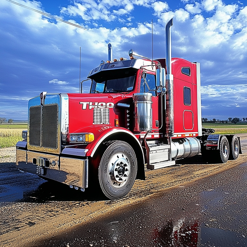
5.2 Commercial Vehicles
- Heavy-duty truck mounts: Higher load capacity (up to 5,000 kg per mount)
- Off-road vehicle designs: Enhanced misalignment accommodation
- Hybridized powertrains: Additional mounts for battery packs and electric components
Special considerations:
- Shock absorption for severe duty cycles
- Corrosion resistance for harsh operating environments
- Maintenance-friendly designs for easy replacement
5.3 Performance and Racing Applications
- Semi-active mounts: Adjustable damping for track conditions
- Lightweight constructions: Carbon fiber or titanium components
- Direct-mount configurations: Minimal compliance for precise throttle response
Technical challenges: Balancing vibration isolation with the need for precise engine feedback in high-performance driving.
6. Design Challenges and Engineering Solutions
6.1 Trade-offs in Mount Design
- Stiffness vs. isolation: Finding optimal balance between secure mounting and vibration attenuation
- Static vs. dynamic performance: Ensuring adequate support under load while maintaining isolation
- Cost vs. performance: Material selection and manufacturing process optimization
Solution approaches:
- Multi-rate mount designs: Combining different stiffness zones in a single mount
- Adaptive control systems: Real-time adjustment of mount characteristics
- Topology optimization: Lightweighting through structural analysis
6.2 Thermal Management
- Heat-resistant materials: Silicone rubbers for high-temperature applications
- Thermal insulation: Preventing heat transfer from exhaust components
- Cooling considerations: Airflow management around mount locations
Testing standard: Mounts must maintain performance after 1,000 hours of thermal cycling between -40°C and +150°C.
6.3 Durability and Fatigue Resistance
- Accelerated aging tests: Simulating 10+ years of service life
- Environmental exposure: Salt spray, UV radiation, and chemical resistance
- Load cycle testing: Mimicking worst-case driving conditions
Quality metrics: Leading manufacturers achieve <0.1% failure rates in field testing through rigorous validation processes.
7. Market Trends and Future Developments
7.1 Electrification and Hybrid Powertrains
- Additional mounting requirements: For battery packs and electric motors
- Active damping adaptation: Responding to electric motor torque ripple
- Thermal management integration: Cooling for high-power electronics
Technical innovation: Some EVs now use magnetorheological mounts that adjust stiffness based on real-time powertrain dynamics.
7.2 Autonomous Vehicle Considerations
- Ultra-quiet cabin requirements: Stricter NVH targets for self-driving systems
- Precision mounting: Maintaining sensor alignment during operation
- Predictive maintenance: Health monitoring of mount condition
Emerging technology: Smart mounts with integrated sensors for real-time vibration monitoring and predictive maintenance alerts.
7.3 Sustainable Manufacturing Initiatives
- Recyclable materials: Bio-based rubber compounds and recyclable metals
- Energy-efficient production: Low-carbon manufacturing processes
- Lightweighting: Reduced material usage through advanced engineering
Research frontier: Development of self-healing rubber compounds that automatically repair minor cracks and damage.
8. Case Studies: Real-World Implementations
Case Study 1: Premium Sedan Engine Mount Upgrade
A European luxury car manufacturer implemented active vacuum mounts in their flagship model, achieving:
- 22% improvement in cabin noise isolation at 20Hz
- 15% reduction in vibration-induced component wear
- Enhanced refinement during rapid acceleration/deceleration
Case Study 2: Commercial Truck Fleet Modernization
A global logistics company upgraded to hydraulic mounts in their heavy-duty trucks, resulting in:
- 30% reduction in driver fatigue complaints
- 25% longer mount service life
- Improved cargo security through reduced vibration-induced movement
Conclusion: The Silent Guardians of Powertrain Performance
Engine mounts may appear as simple components, but their role in ensuring vehicle refinement, durability, and performance is absolutely critical. As automotive technologies continue evolving toward electrification and autonomy, these interfaces will become even more sophisticated:
Key takeaways:
- Modern engine mounts combine mechanical, hydraulic, and electronic technologies for comprehensive vibration control
- Advanced materials and adaptive control systems are pushing performance boundaries
- System integration with electrified powertrains requires new engineering solutions
- Sustainability and digitalization are shaping the next generation of mount technologies
Final thought: In the pursuit of quieter, more comfortable, and more efficient vehicles, engine mounts represent the often-overlooked but absolutely essential components that silently protect passengers from the raw power of internal combustion—and will continue to play this vital role even as propulsion technologies evolve. The future of mobility depends on these unsung heroes to deliver unprecedented levels of refinement and reliability.
Call to Action
🔧 Upgrading your vehicle’s powertrain?
⚙️ Consider advanced engine mounts for superior NVH performance
📊 Request technical specifications comparing different mount technologies
#AutomotiveEngineering #EngineMounts #NVHEngineering #VehicleDynamics #PowertrainTechnology #AdvancedMaterials #SustainableMobility #FutureOfTransportation