
In the intricate symphony of automotive engineering, the drive shaft serves as the unsung hero that seamlessly transfers rotational power from the transmission to the wheels while accommodating dynamic vehicle movements. This critical component must simultaneously handle extreme torque loads, compensate for suspension travel, and maintain precision alignment under varying operating conditions. This comprehensive technical analysis explores the engineering marvels behind drive shaft design, material innovations, dynamic performance characteristics, and the evolving role of drive shafts in next-generation vehicle architectures.


1. Fundamental Role of Drive Shafts in Power Transmission
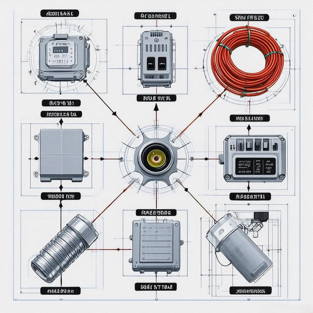
Drive shafts represent the critical mechanical link between the engine’s power generation and the wheels’ traction, performing several essential functions:
- Torque transmission: Efficiently transferring rotational force from transmission to differential
- Misalignment compensation: Accommodating angular, parallel, and axial displacements
- Vibration isolation: Minimizing driveline disturbances reaching the passenger compartment
- Weight optimization: Balancing strength requirements with fuel efficiency demands
Technical significance: Modern drive shafts must handle torque loads exceeding 1,000 Nm in performance vehicles while maintaining rotational speeds up to 10,000 RPM in electric powertrains.
2. Types of Drive Shafts and Configuration Variations
Contemporary vehicles employ various drive shaft configurations optimized for specific drivetrain layouts:
2.1 Single-Piece Drive Shafts
- Design: Solid or tubular construction with universal joints at both ends
- Applications: Rear-wheel drive trucks and SUVs
- Advantages:
- Simple, robust construction
- Cost-effective manufacturing
- Easy maintenance and replacement
Performance metrics:
- Typical length: 1.0-1.5 meters
- Torque capacity: Up to 800 Nm
- Operating speed: 3,000-6,000 RPM
2.2 Two-Piece Drive Shafts
- Design: Split design with intermediate support bearing
- Applications: Front-engine, rear-wheel drive passenger cars
- Advantages:
- Better NVH (Noise, Vibration, Harshness) characteristics
- Reduced critical speed concerns
- Improved weight distribution
Technical specifications:
- Intermediate bearing load capacity: 500-800 kg
- Joint angle compensation: Up to 4° angular misalignment
- Weight reduction: 15-20% compared to single-piece designs
2.3 Composite Drive Shafts
- Design: Carbon fiber or fiberglass reinforced polymer tubes
- Applications: High-performance and electric vehicles
- Advanced features:
- Torque capacity: 500-1,200 Nm
- Weight savings: 40-60% vs. steel shafts
- Damping characteristics: Natural vibration attenuation
Material innovations:
- Hybrid composites with aluminum cores for strength
- Nanofiber reinforcements for impact resistance
- Surface treatments for UV and moisture protection
2.4 Constant Velocity (CV) Drive Shafts
- Design: Double-cardan or Rzeppa joint configurations
- Applications: Front-wheel drive and all-wheel drive vehicles
- Performance benefits:
- Constant speed operation regardless of joint angle
- Smoother power transmission at extreme angles
- Reduced vibration compared to universal joints
Technical specifications:
- Maximum operating angle: 45-50° (CV joints)
- Torque capacity: 300-1,500 Nm
- Efficiency: >98% power transmission
3. Advanced Material Formulations and Engineering Innovations
3.1 Steel Alloys for High-Strength Applications
- Chromium-molybdenum steel (4130/4340):
- Tensile strength: 800-1,200 MPa
- Fatigue resistance: 10^7 cycles at 50% yield strength
- Heat treatment: Quenching and tempering for optimal properties
Manufacturing processes:
- Seamless tube extrusion for consistent wall thickness
- CNC machining for precision end machining
- Induction hardening for wear resistance at critical points
3.2 Aluminum Alloys for Weight Reduction
- 6061-T6 aluminum:
- Density: 2.7 g/cm³ (35% lighter than steel)
- Yield strength: 270 MPa
- Corrosion resistance: Excellent with proper surface treatment
Design considerations:
- Increased wall thickness to compensate for lower strength
- Reinforcement rings at high-stress locations
- Specialized anodizing for wear protection
3.3 Composite Materials for Advanced Applications
- Carbon fiber reinforced polymers (CFRP):
- Specific stiffness: 200 GPa/(g/cm³)
- Fatigue life: >10^8 cycles
- Impact resistance: Superior to metallic materials
Manufacturing techniques:
- Filament winding for precise fiber orientation
- Autoclave curing for optimal resin impregnation
- Automated fiber placement for complex geometries
4. Dynamic Performance Characteristics and Testing
4.1 Critical Speed Analysis
- Natural frequency calculation:
- Formula: n = (1/2π)√(k/m)
- Where k = stiffness, m = mass
- Operating speed margins:
- Typically maintain 15-20% clearance below critical speed
- Balancing requirements:
- G2.5 balance quality for passenger vehicles
- G1.0 for performance applications
Testing methods:
- Spin testing to 125% of maximum operating speed
- Modal analysis with laser vibrometry
- Operational deflection shape measurement
4.2 Vibration and Noise Characteristics
Common vibration modes:
- First bending mode: Typically 500-1,500 Hz
- Torsional vibration: Related to engine firing frequency
- Critical speed excitation: When rotation matches natural frequency
Noise reduction strategies:
- Specially designed joints: Minimize impact noise during operation
- Damping materials: Constrained layer damping treatments
- Precision balancing: Reducing vibration at source
Measurement standards:
- ISO 362 for vehicle pass-by noise testing
- SAE J2380 for electric vehicle drive unit noise
4.3 Durability and Fatigue Testing
Accelerated testing protocols:
- Lifing tests: 10^7 cycles at maximum torque
- Environmental testing:
- Temperature cycling: -40°C to +120°C
- Corrosion testing: Salt spray per ASTM B117
- Chemical resistance: Fuel, oil, and coolant exposure
Failure mode analysis:
- Crack initiation sites: Typically at welds or joint interfaces
- Progressive damage modeling: Using finite element analysis
- Remaining useful life prediction: Based on cumulative damage
5. System Integration and Vehicle Applications
5.1 Conventional Rear-Wheel Drive Vehicles
- Typical configuration: Single-piece or two-piece steel shaft
- Key requirements:
- High torque capacity (800-1,200 Nm)
- Robust joint design for off-road conditions
- Proper phasing with differential gears
Performance metrics:
- Torque transfer efficiency: >97%
- Vibration isolation: <0.1g acceleration at cabin
- Service life: 150,000-200,000 km
5.2 Front-Wheel Drive and All-Wheel Drive Systems
- CV joint requirements:
- Compact design for tight packaging
- High-angle operation (up to 50°)
- Precise backlash control
Special considerations:
- On-demand AWD systems: Rapid engagement/disengagement
- Torque vectoring: Differential speed control between shafts
- Electric motor integration: High-speed operation (10,000+ RPM)
5.3 Electric and Hybrid Powertrains
- E-drive shafts:
- Higher rotational speeds (5,000-15,000 RPM)
- Lower torque but higher speed requirements
- Integrated inverter mounting
Emerging trends:
- Integrated motor-transmission-shaft assemblies:
- Reduced component count
- Improved power density
- Compact packaging
Special materials:
- High-speed bearings: Ceramic or hybrid designs
- Advanced lubrication: Molybdenum disulfide coatings
6. Design Challenges and Engineering Solutions
6.1 Balancing Weight Reduction and Strength
Solution approaches:
- Topology optimization: Using FEA to remove unnecessary material
- Hybrid material construction: Aluminum shafts with steel joints
- Advanced manufacturing: Hollow shafts with internal ribs
Performance targets:
- Weight reduction: 20-40% vs. conventional designs
- Strength retention: >90% of original capacity
6.2 Accommodating Dynamic Vehicle Movements
Key design features:
- Splined joints: Allow axial movement
- Universal/CV joints: Compensate for angular misalignment
- Flexible couplings: Absorb torsional vibrations
Movement accommodation:
- Longitudinal travel: Up to 150mm in off-road applications
- Angular variation: ±5° during suspension travel
- Torsional compliance: 1-2° torsional deflection
6.3 Ensuring Precision Alignment
Alignment control methods:
- Laser alignment tools: Sub-millimeter precision
- Preload bearings: Maintaining proper joint angles
- Flexible mounts: Absorbing minor misalignments
Tolerance specifications:
- Axial alignment: ±0.1mm
- Angular alignment: ±0.5°
- Radial runout: <0.05mm
7. Testing and Validation Protocols
7.1 Component-Level Testing
Mechanical testing:
- Torque-to-failure: 150% of maximum rated torque
- Bending fatigue: 10^7 cycles at 75% rated torque
- Impact testing: Simulated road hazards
Environmental testing:
- Temperature cycling: -40°C to +150°C
- Corrosion resistance: Salt spray, humidity, and chemical exposure
- UV aging: Accelerated weathering tests
7.2 Vehicle-Level Validation
Dynamometer testing:
- Torque ramp tests: Gradual load application
- Endurance cycles: 1,000+ hours of continuous operation
- NVH analysis: Cabin noise and vibration measurements
Road testing:
- Test matrix:
- Urban driving (stop-and-go conditions)
- Highway cruising (steady-state operation)
- Off-road conditions (extreme angles and impacts)
- Data acquisition: Strain gauges, accelerometers, and temperature sensors
7.3 Digital Validation Methods
Simulation tools:
- Multi-body dynamics (MBD): Full vehicle driveline simulation
- Finite element analysis (FEA): Stress and fatigue prediction
- Computational fluid dynamics (CFD): For high-speed shaft cooling
Virtual testing advantages:
- Reduced development time
- Early detection of potential issues
- Optimized design parameters
8. Market Trends and Future Developments
8.1 Electrification and High-Speed Drives
- Increased RPM requirements: Up to 15,000 RPM for e-axles
- Advanced balancing techniques: Magnetic bearings for ultra-high speeds
- Integrated cooling systems: Oil or air cooling for high-performance applications
Technical challenges:
- Bearing selection: Ceramic or hybrid designs for high-speed operation
- Material selection: High-strength, low-density materials
- NVH control: Advanced damping for electric motor integration
8.2 Lightweighting and Material Innovations
- Carbon fiber composites:
- Potential weight savings: 60-70% vs. steel
- Challenges: Cost and manufacturing complexity
- Aluminum alloys:
- New alloys with improved strength-to-weight ratios
- Advanced manufacturing techniques (friction stir welding)
Sustainability focus:
- Recyclable materials: End-of-life considerations
- Bio-based composites: Renewable material sources
- Energy-efficient manufacturing: Reduced carbon footprint
8.3 Smart and Adaptive Drive Shafts
- Integrated sensors:
- Torque and vibration monitoring
- Predictive maintenance capabilities
- Active control systems:
- Adjustable joint stiffness
- Real-time misalignment compensation
Emerging technologies:
- Shape-memory alloys: Self-adjusting joint angles
- Piezoelectric dampers: Active vibration control
- Digital twins: Virtual representations for predictive maintenance
Conclusion: The Dynamic Link of Modern Powertrains
Drive shafts represent a critical yet often overlooked component that enables the efficient transfer of power from engine to wheels while accommodating the dynamic movements inherent in vehicle operation. As automotive technologies evolve toward electrification, autonomous driving, and lightweight construction, drive shafts must continue adapting to meet new challenges:
Key takeaways:
- Modern drive shafts combine advanced materials, precision engineering, and sophisticated joint designs
- Electric powertrains introduce new requirements for high-speed operation and NVH control
- Lightweighting efforts are pushing the boundaries of material science and manufacturing
- Smart, adaptive drive shafts represent the future of intelligent powertrain systems
Final thought: In the pursuit of more efficient, responsive, and comfortable vehicles, drive shafts continue to evolve from simple torque transmitters to sophisticated components that actively contribute to vehicle dynamics and performance. The next generation of mobility will depend on these dynamic links to efficiently channel power while providing unprecedented levels of refinement and reliability.
Call to Action
🔧 Upgrading your vehicle’s drivetrain?
⚙️ Consider advanced drive shaft solutions for improved performance and efficiency
📊 Request technical specifications comparing different drive shaft configurations
#AutomotiveEngineering #DriveShaftTechnology #PowertrainInnovation #VehicleDynamics #ElectricVehicles #AdvancedMaterials #SustainableMobility #FutureOfTransportation
