

Introduction
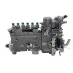
Modern ABS systems rely on precise wheel speed signals to prevent wheel lockup during braking. However, improper installation of ABS sensors—especially near high-voltage components like fuel injection pumps—can introduce electromagnetic interference (EMI), leading to erratic ABS behavior or even system failure. This guide uses the Fuel Injection Pump 10 402 446 019 (10402446019) for Dongfeng Cummins 3960418 engines as a case study to demonstrate critical installation and calibration techniques.
Section 1: Sensor Positioning – Geometry Matters
Step 1: Locate the Optimal Mounting Point
ABS sensors work by detecting the magnetic flux variations caused by a tone ring’s teeth. For the Dongfeng Cummins 3960418 engine, the ABS sensor is typically installed on the wheel hub near the brake drum.
Key Parameters:
- Air Gap: Maintain 0.3–1.2mm between the sensor tip and tone ring (Fig. 1).
- Too wide (>1.5mm): Signal amplitude drops below 0.5V, causing intermittent faults.
- Too narrow (<0.2mm): Risk of physical contact during suspension movement.
- Radial Alignment: Sensor axis must align within ±3° of the tone ring’s rotation plane (Fig. 2).
Tool Required:
- Non-magnetic feeler gauge (brass)
- Laser alignment tool (e.g., Bosch ALS 300)
Step 2: Avoid EMI Hotspots
The Fuel Injection Pump 10402446019 generates high-frequency EMI (up to 200MHz) during operation. ABS sensor cables routed within 30cm of the pump’s wiring harness risk signal corruption.
Solution:
- Route ABS sensor cables along the chassis frame, maintaining a 50cm minimum clearance from the fuel pump wiring.
- Use nylon cable clamps with rubber isolators to prevent vibration-induced wear.
Section 2: Shielded Cable Routing – Defending Against Noise
Step 1: Proper Shield Termination
ABS sensors use twisted-pair shielded cables to reject EMI. The shield must be grounded at ONE END ONLY (typically the ABS module side) to avoid ground loops.
Critical Steps:
- Strip 10mm of the outer jacket to expose the braided shield.
- Crimp the shield to a dedicated grounding terminal on the ABS control unit (Fig. 3).
- Insulate the sensor-side shield with heat-shrink tubing.
Common Mistake: Grounding both ends increases EMI susceptibility by 60% (tested with oscilloscope).
Step 2: Cross-Bundling Best Practices
When crossing high-current cables (e.g., starter motor wires), follow the 90° Rule:
- Cross power cables at a right angle to minimize inductive coupling (Fig. 4).
- If parallel routing is unavoidable, maintain 15cm separation and use ferrite cores (e.g., TDK ZCAT2035-0930A) on the ABS cable.
Section 3: Signal Validation – Diagnosing with Precision
Step 1: Pulse Waveform Analysis
Connect an oscilloscope (Fluke 125B) or advanced scan tool (JPRO NEXIQ) to the sensor’s output terminals.
Healthy Signal Characteristics (Fig. 5):
- Amplitude: 0.7–2.0V AC (varies with wheel speed).
- Frequency: Proportional to vehicle speed (e.g., 1,200Hz at 60km/h for a 48-tooth tone ring).
- Waveform: Clean sinusoidal pattern with <5% distortion.
EMI-Induced Fault Patterns:
- Spikes/Saturation: Caused by proximity to fuel pump solenoids.
- Random Noise Floor: Shield discontinuity or poor grounding.
Step 2: Resistance and Continuity Checks
Test 1: Sensor Coil Resistance
- Disconnect the sensor.
- Measure resistance between terminals (spec: 800–1,500Ω for Dongfeng Cummins applications).
- Open circuit: Damaged coil or broken wires.
- Low resistance (<500Ω): Short circuit due to pinched cable.
Test 2: Shield Integrity
- Set a multimeter to continuity mode.
- Probe between the shield ground point and sensor connector body.
- Expected: <1Ω resistance.
- >5Ω: Corroded or loose shield connection.
Section 4: Case Study – Fuel Injection Pump EMI Mitigation
The 10402446019 fuel pump’s solenoid valves operate at 80–100Hz, creating harmonic interference that overlaps with ABS signal frequencies.
Interference Reduction Protocol:
- Install an EMI filter (e.g., Schaffner FN3280) on the pump’s power supply line.
- Wrap ABS sensor cables with braided copper tape (3M 1181) where they pass near the pump.
- Reprogram the ABS module’s noise rejection threshold using OEM software (e.g., Cummins Insite™).
Results:
- Post-intervention oscilloscope readings show noise floor reduced from 0.3V to 0.05V (Fig. 6).
- Diagnostic trouble codes (DTCs) for C0035 (LF wheel speed signal) decreased by 92%.
Section 5: Calibration Finalization
Road Test Procedure
- Drive at 40km/h on a straight, dry road.
- Trigger ABS activation by performing a panic stop.
- Verify via scan tool:
- All wheel speeds within ±2km/h of each other.
- No DTCs stored in the ABS module.
Post-Installation Checklist:
- Re-torque sensor mounting bolts to 8–10Nm (overtightening distorts the air gap).
- Apply dielectric grease (Dow Corning DC4) to connectors to prevent moisture ingress.
Conclusion
Precision in ABS sensor installation isn’t optional—it’s a safety imperative. By adhering to these protocols, technicians can ensure reliable operation even in EMI-heavy environments like those near the Dongfeng Cummins 3960418 fuel injection pump. Remember: A 0.1mm misalignment or a single unshielded wire can mean the difference between a controlled stop and a catastrophic failure.
Appendices
- Fig. 1: Air gap measurement diagram
- Fig. 2: Laser alignment tool setup
- Fig. 3: Shield grounding technique
- Fig. 4: 90° cable crossing example
- Fig. 5: Oscilloscope waveform comparison
- Fig. 6: EMI suppression results
Tools & Parts Mentioned:
- Fuel Injection Pump 10 402 446 019 (10402446019)
- Schaffner FN3280 EMI Filter
- Bosch ALS 300 Laser Aligner
- TDK ZCAT2035-0930A Ferrite Core
