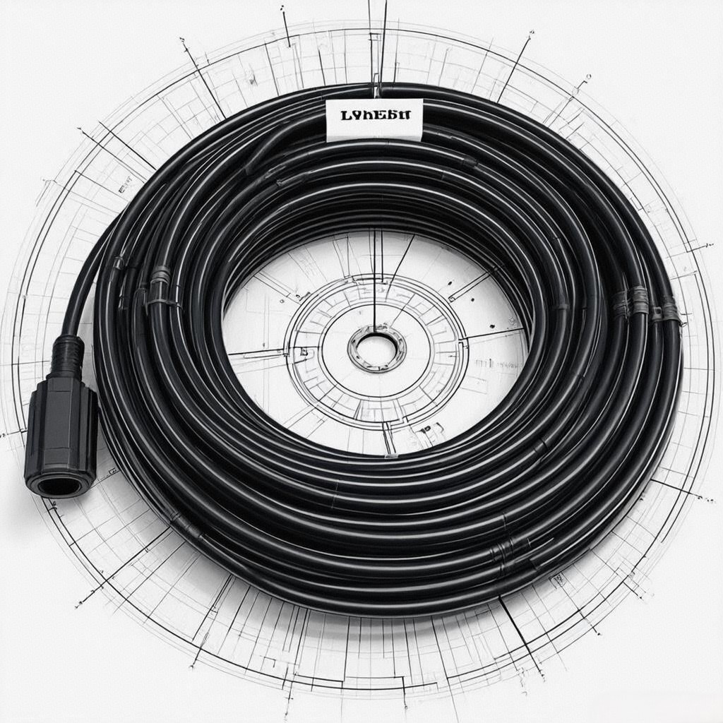
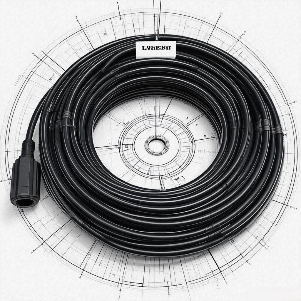
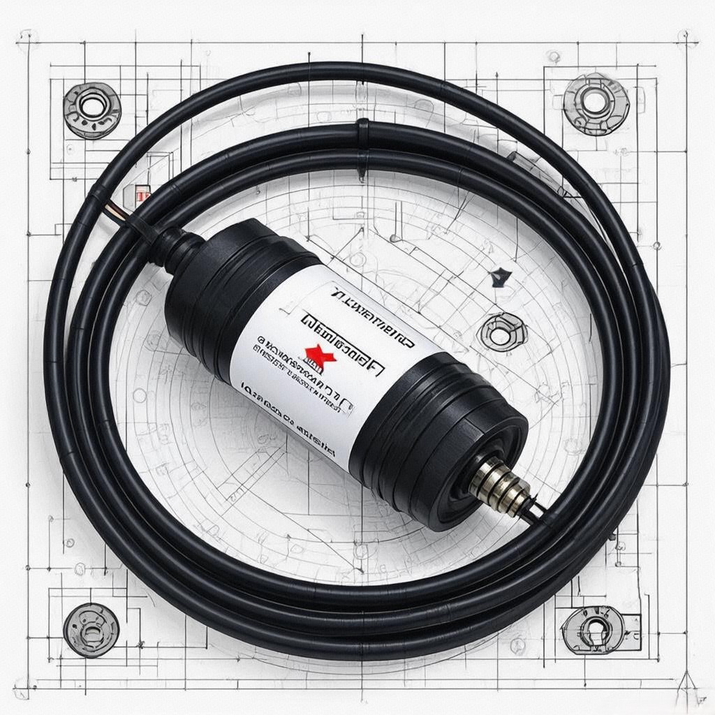
In the intricate nervous system of modern vehicles, sensor cable assemblies serve as the vital conduits that transmit critical data between sensors and electronic control units (ECUs). These specialized wiring harnesses must reliably convey signals across increasingly complex vehicle architectures while withstanding harsh operating conditions. This comprehensive technical analysis explores the engineering behind sensor cable assemblies, their critical role in vehicle systems, and the advanced technologies shaping their evolution in the era of autonomous driving and electrification.


1. Fundamental Role of Sensor Cable Assemblies in Vehicle Systems
Sensor cable assemblies represent the physical layer of vehicle sensor networks, performing several mission-critical functions:
- Signal transmission: Carrying analog and digital signals from sensors to ECUs
- Power delivery: Supplying low-voltage power to sensor elements
- EMI shielding: Protecting sensitive signals from electromagnetic interference
- Mechanical durability: Withstanding vibration, temperature extremes, and fluid exposure
Technical specifications:
- Signal transmission speed: Up to 150Mbps for high-speed CAN FD
- Operating temperature range: -40°C to +125°C
- Voltage ratings: 3.3V, 5V, and 12V systems
- Current capacity: 1-10A depending on application
Industry significance: Modern vehicles contain 50-100 sensor cable assemblies, with the total wiring harness weight approaching 50kg in premium models. The reliability of these assemblies directly impacts 60% of vehicle electronic system failures.
2. Core Components and Construction Features
2.1 Conductors and Insulation Materials
Conductor types:
- Copper alloys: Oxygen-free copper (OFC) for high conductivity
- Aluminum alloys: Lightweight alternative with tin-plating
- Hybrid designs: Copper cores with aluminum shielding
Insulation materials:
- XLPE (Cross-linked polyethylene): Temperature rating up to 125°C
- Teflon (PTFE): Extreme temperature resistance (-60°C to +200°C)
- PVC (Polyvinyl chloride): Cost-effective for standard applications
Stranding configurations:
- Fine-stranded wires: 7/0.3mm for flexibility in tight spaces
- Solid-core conductors: For fixed installations
- Multi-strand configurations: Balanced flexibility and current capacity
2.2 Shielding and Grounding Systems
EMI protection:
- Braided shields: 85-95% coverage for optimal EMI rejection
- Foil shielding: Aluminum/polyester laminates for high-frequency noise
- Combination shields: Braided + foil for comprehensive protection
Grounding methods:
- Dedicated ground wires: Separate return paths for critical signals
- Chassis bonding: Direct connection to vehicle ground points
- Capacitive coupling: For high-frequency noise suppression
Performance metrics:
- Shielding effectiveness: >60dB attenuation at 100MHz
- Transfer impedance: <100mΩ/m for braided shields
- Ground loop resistance: <0.1Ω for critical systems
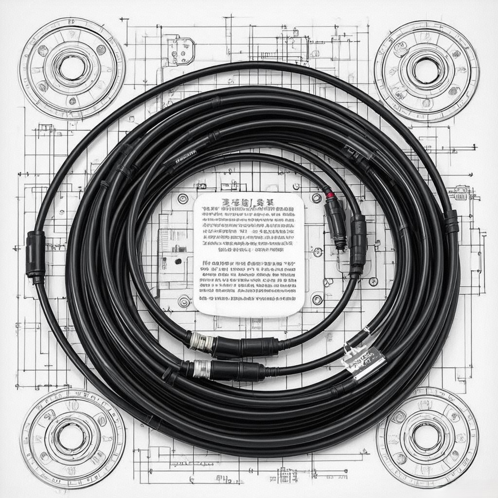
2.3 Connectors and Termination Systems
Connector types:
- Sealed connectors: IP67/IP69K rated for harsh environments
- High-density connectors: 200+ pins for advanced ECUs
- Modular designs: Quick-disconnect for serviceability
Termination methods:
- Crimped connections: Precision tooling for consistent quality
- Soldered joints: For high-reliability applications
- Insulation displacement: High-volume manufacturing
Contact materials:
- Phosphor bronze: With gold plating (0.8-3μm thickness)
- Copper alloys: Silver plating for high-current applications
- Stainless steel: For mechanical strength in harsh conditions


3. Advanced Design Considerations
3.1 Electromagnetic Compatibility (EMC)
Design strategies:
- Twisted pair configurations: Differential signaling for noise rejection
- Ground plane integration: Continuous shielding throughout harness
- Filtering components: Common-mode chokes and ferrite beads
Testing standards:
- ISO 11452-2: Bulk current injection testing
- ISO 7637-2: Transient immunity testing
- CISPR 25: Radiated emissions testing
3.2 Thermal Management
Heat dissipation techniques:
- Cross-sectional area optimization: Current-carrying capacity calculations
- Insulation selection: Temperature-rated materials
- Routing considerations: Away from heat sources
Thermal protection:
- Fuses and PTC devices: Overcurrent protection
- Thermal sensors: Monitoring critical junctions
- Heat shields: Reflective barriers for high-temperature areas
3.3 Mechanical Durability
Vibration resistance:
- Strain relief designs: Secure terminations at both ends
- Cable clamps: Preventing chafing and movement
- Flexible sections: Accommodating suspension travel
Environmental protection:
- Molded boots: IP67 rated for water ingress
- Chemical resistance: Fuel, oil, and coolant compatibility
- UV stabilization: For exterior routing


4. System Integration and Vehicle Applications
4.1 Powertrain Systems
Engine control applications:
- Crankshaft position sensors: High-resolution timing signals
- Throttle position sensors: Precise analog voltage transmission
- Coolant temperature sensors: Low-current resistance signals
Transmission control:
- Speed sensors: Differential signaling for noise immunity
- Pressure sensors: Shielded cables for EMI protection
- Shift solenoid controls: High-speed PWM signals
Performance metrics:
- Signal integrity: <1% voltage drop over full length
- Response time: <1ms for critical control loops
- Reliability: 1,000,000+ cycles at rated load
4.2 Chassis and Safety Systems
Brake system applications:
- Wheel speed sensors: Shielded twisted pairs for ABS signals
- Brake pressure sensors: High-impedance voltage transmission
- Pedal position sensors: Redundant signal paths
Steering and suspension:
- Torque sensors: Low-noise analog signal transmission
- Level sensors: High-impedance voltage signals
- Actuator controls: High-speed CAN bus communication
Safety critical features:
- Dual-channel redundancy: For fail-operational systems
- Signal validation: Cross-checking between redundant paths
- Fault detection: Real-time monitoring of continuity and shorts
4.3 Body and Convenience Systems
Interior sensing applications:
- Occupant detection sensors: Low-voltage DC signals
- Light sensors: High-impedance analog outputs
- Rain sensors: Capacitive signal transmission
Infotainment systems:
- Microphone arrays: Balanced audio signal pairs
- Camera feeds: High-speed differential signaling
- Control interfaces: Shielded USB and Ethernet cables
Comfort systems:
- Seat position sensors: Potentiometer signal transmission
- Climate control sensors: Low-current voltage signals
- Sunroof controls: PWM signal transmission

5. Design Challenges and Engineering Solutions
5.1 Signal Integrity in High-Speed Systems
Technical challenges:
- Crosstalk between adjacent wires: Minimizing interference
- Signal attenuation: Maintaining integrity over long runs
- Impedance matching: Preventing reflections
Solution approaches:
- Differential signaling: Twisted pair configurations
- Characteristic impedance control: 90-120Ω for high-speed signals
- Termination resistors: Properly matched to cable impedance
5.2 Electromagnetic Compatibility in Complex Environments
Design measures:
- Shielded enclosures: Continuous grounding paths
- Filtering components: Common-mode chokes
- Routing segregation: Separating power and signal cables
Testing protocols:
- EMI pre-compliance testing: Early identification of issues
- Full-vehicle EMC testing: Validating system performance
- Component-level shielding: For particularly sensitive circuits
5.3 Weight and Cost Optimization
Material innovations:
- Aluminum alloys: Weight reduction with proper termination
- High-conductivity copper: Optimized for current density
- Miniaturized connectors: Higher density packaging
Design strategies:
- Cable consolidation: Combining multiple signals where possible
- Route optimization: Shortest path with minimal bends
- Standardized components: Reducing inventory complexity
6. Testing and Validation Methodologies
6.1 Component-Level Testing
Conductor testing:
- Continuity verification: Megohmmeter testing
- Resistance measurement: 4-wire Kelvin method
- Insulation resistance: High-voltage testing
Shielding effectiveness:
- Transfer impedance: Network analyzer measurements
- Shield current monitoring: Detecting leakage paths
- EMI susceptibility: Controlled field exposure
Connector testing:
- Contact resistance: Micro-ohmmeter measurements
- Mating cycles: Durability testing (10,000+ cycles)
- Environmental sealing: Pressure and vacuum testing
6.2 System-Level Validation
Vehicle testing protocols:
- Vibration testing: 15g RMS acceleration for 1,000 hours
- Temperature cycling: -40°C to +125°C, 1,000 cycles
- Fluid exposure: Fuel, oil, and coolant resistance
Performance metrics:
- Signal integrity: <2% voltage drop under load
- EMI performance: Compliance with ISO 11452-2
- Mechanical reliability: No failures during vibration testing
6.3 Virtual Validation
Simulation tools:
- Electromagnetic field solvers: CST Studio Suite
- Thermal analysis: ANSYS Thermal
- Mechanical stress analysis: Abaqus/Explicit
Test scenarios:
- 10,000+ virtual test cases covering all operating conditions
- Edge case testing: Extreme temperatures and vibrations
- Long-term durability simulation: 10-year equivalent cycles
7. Market Trends and Future Developments
7.1 Electrification and High-Voltage Systems
Key innovations:
- High-voltage insulation: Up to 1,000V systems
- Current sensing integration: Embedded shunt resistors
- Thermal management: Active cooling for high-power cables
Technical challenges:
- Safety insulation: Preventing arcing and short circuits
- Signal isolation: Galvanic separation for safety systems
- Weight reduction: Without compromising performance
7.2 Advanced Materials and Manufacturing
Innovative approaches:
- Nanocomposite insulation: Enhanced thermal and electrical properties
- Additive manufacturing: Custom connector designs
- Automated assembly: Robotic termination systems
Sustainability focus:
- Recyclable materials: End-of-life considerations
- Energy-efficient manufacturing: Reduced carbon footprint
- Smart materials: Self-diagnostic capabilities
7.3 Smart and Connected Vehicle Integration
Emerging technologies:
- Sensor fusion cabling: Dedicated high-speed links for ADAS
- Power-over-data lines: Combining power and signal transmission
- Predictive maintenance: Embedded health monitoring sensors
User benefits:
- Faster data rates: Support for autonomous driving systems
- Reduced weight: Optimized cable routing
- Improved reliability: Self-diagnostic capabilities
8. Case Studies: Real-World Implementations
Case Study 1: Premium Electric Vehicle High-Voltage Harness
A leading EV manufacturer implemented a high-voltage sensor cable assembly for their latest model, achieving:
- 30% weight reduction compared to previous generation
- 400V system compatibility with safety insulation
- Compliance with ISO 6469-3 electrical safety standards
Case Study 2: Autonomous Driving Sensor Fusion Harness
A Tier 1 supplier developed a specialized harness for sensor fusion applications, featuring:
- 10Gbps data transmission capacity
- Shielded twisted pairs for LiDAR and radar signals
- Integrated power delivery for camera systems


Conclusion: The Nervous System of Modern Vehicles
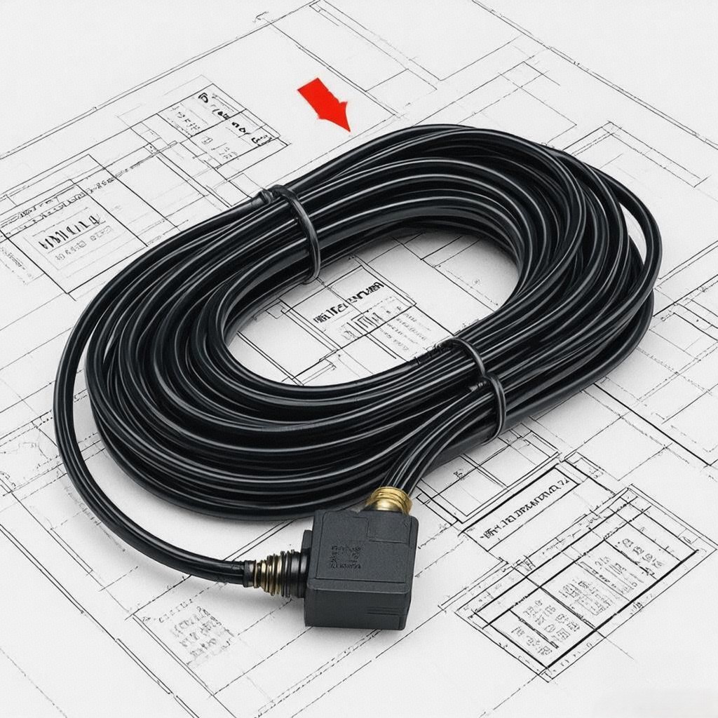
Sensor cable assemblies represent the critical physical layer that enables vehicle sensor networks to function reliably in increasingly complex environments. As vehicles become more electrified, autonomous, and connected, these assemblies must continue evolving to meet new challenges while maintaining the highest standards of safety and reliability.
Key takeaways:
- Modern sensor cable assemblies combine specialized conductors, shielding, and connectors for reliable signal transmission
- System integration requires careful consideration of EMI, thermal, and mechanical factors
- Electrification and autonomy are driving innovations in high-voltage and high-speed cabling
- Sustainability and digitalization are shaping the future of wiring harness design
Final thought: The sensor cable assembly may be the unsung hero of modern vehicle electronics, but its importance cannot be overstated. As we move toward a future of fully autonomous, electric vehicles, the reliability and performance of these critical components will be more important than ever in ensuring safety and functionality on the road.
Call to Action
🔧 Designing a new vehicle system?
⚙️ Explore our advanced sensor cable assembly solutions
📊 Request custom design support for your specific application
#SensorCableAssembly #VehicleElectronics #AutomotiveEngineering #EMCDesign #ThermalManagement #AdvancedMaterials #SmartMobility #FutureOfTransportation #FunctionalSafety #Electrification
